A power station stores direct current. Every socket on its front panel wants alternating current. The inverter is the block that makes the conversion. Its rating is the ceiling on everything the machine will ever run. Two stages make up the working principle of a 5000 watt inverter. Every half cycle, a 230 volt RMS output peaks at 325 volts. The first stage has to lift the pack above that figure. The second chops the raised bus back down into a sine at 50 hertz. Two construction families dominate. They both produce a clean waveform at the socket. Everything turns on the transformer. That one component decides weight, surge, idle draw and efficiency together.
A high-frequency design switches the direct current at 20 to 100 kilohertz and passes it through a small ferrite-cored transformer. Ferrite works at those frequencies where iron can’t. Run a transformer that fast and it needs almost no core material. Efficiency reads high. Published figures run 95 to 98 percent, with idle draw starting around 30 watts on the better units. Thirty watts running around the clock is 720 watt-hours. On a 1 kilowatt-hour machine left switched on between jobs, idle power consumption eats into runtime by close to three quarters before a single tool gets plugged in. The 95 to 98 percent is a peak at one particular load. Most of reading an inverter efficiency rating comes down to asking which load produced it, since a unit at a tenth of its rating never reaches the printed figure.
The cost lands on surge. A 2 kilowatt high-frequency unit typically delivers 3 to 4 kilowatts for 3 to 5 seconds. Portable machines almost all use this family, since a compact case leaves no room for iron.
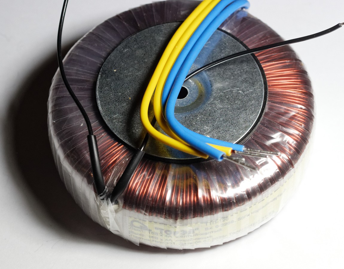
A mains-frequency toroidal transformer, copper wound on an iron ring. Energy stored in a core like this is what holds a motor through its starting seconds. Photo in the public domain.
A low-frequency design uses a transformer wound on an iron core running at 50 or 60 hertz, matching the output frequency. That core is physically large. It stores a great deal of energy. Stored energy is what a motor wants at the moment it starts. A 2 kilowatt low-frequency unit delivers 6 to 10 kilowatts of surge and holds it for 10 seconds or more. All of that stored energy exists for the surge support that starting heavy appliances asks for. Twenty seconds at three times the continuous rating is a common published figure on the iron side. Inside that window a compressor can pull its starting current for a second or two with room to spare. Ferrite units typically manage twice the continuous figure for a few hundred milliseconds. The core sets the gap between continuous load and peak surge power. Two machines with identical continuous ratings can behave nothing alike at the moment a compressor kicks in.
The bill arrives as mass and idle consumption. Efficiency sits around 85 percent. Published idle figures start at 180 watts. Inverters of this type are floor-standing objects.
Published figures for the two inverter constructions. The output waveform can be identical in both columns.
Property
High frequency
Low frequency
Transformer core
ferrite
iron
Switching frequency
20 to 100 kHz
50 or 60 Hz
Typical efficiency
95 to 98 percent
around 85 percent
Published idle draw
from about 30 W
180 W and up
Surge on a 2 kW unit
3 to 4 kW for 3 to 5 s
6 to 10 kW for 10 s and more
Mass and volume
compact
large and heavy
What the transformer decides downstream
Topology decides more than the specification sheet admits. Following one choice through the machine shows why. Start with the transformer, since everything else hangs off it. A ferrite core at 50 kilohertz can be a few centimetres across. That sets the size of the case, which sets what a person can carry, which is the whole product category. At 50 hertz an iron core has to be sized for the flux at that frequency. It arrives measured in kilograms. Every one of those kilograms is mass a portable machine can’t spend. Efficiency follows that fork too. Switching losses at high frequency are real. Modern devices have pushed them low enough that the family reaches 95 to 98 percent. An iron transformer carries copper and core losses that sit there whenever the machine is powered. Idle draw is that story measured differently, since a large core magnetised at mains frequency draws its magnetising current whether or not anything is plugged in. Surge reverses the ranking completely. Energy stored in a magnetic core is available instantly. An iron core holds enough of it to carry a motor through its starting seconds. A ferrite core holds little, which leaves the design to survive on its capacitors and its silicon. The waveform itself sits outside all of this. The output stage settles how a pure sine wave differs from a modified sine wave. Total harmonic distortion is the measurement that splits them, under 3 percent on one side and around 25 percent on the other. That 25 percent comes from a stepped square with a dead band at the zero crossing. The transformer feeding either shape has no say in which one comes out. There is a fairly short answer to why precision equipment needs a pure sine wave. Manufacturer compatibility lists name laser printers, photocopiers, dimmers, fan speed controls, mains-timed clocks in coffee makers and microwaves, and transformerless devices such as razors and smoke detectors. Those clocks give the mechanism away. They count zero crossings. Because nothing crosses zero cleanly, they miscount. Switching the output frequency between 50 and 60 hertz happens in firmware on modern designs, which is why a unit sold into a 60 hertz market and one sold into a 50 hertz market can share a part number. Everything about implementing a dual voltage 110 and 220 volt output comes down to how the output winding is tapped. Neither family has an advantage there. A specification sheet lists all of this in one column, which hides how little the entries have to do with each other.
Reading a specification sheet gets easier once that fork is visible. A light machine with a modest surge figure is a high-frequency design whatever the marketing says. A heavy machine with a surge figure three times its continuous rating has iron inside it. Isolation is the other property the iron brings. A mains-frequency transformer separates the output winding from the input side completely. No conductive path runs between the pack and the socket. A high-frequency design can provide isolation too, at its own transformer. Some transformerless topologies dispense with it altogether. That choice reaches the earthing arrangement on the front panel. Silicon carries the difference in the other direction. Devices switching at 50 kilohertz spend a fraction of each cycle in transition. Every one of those transitions costs energy, which is what sets the upper limit on switching frequency for a given device technology. Faster switching shrinks the transformer further. It also heats the semiconductors. Where those two curves cross is where the design settles.
Matching the output, and reading its efficiency
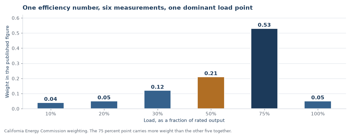
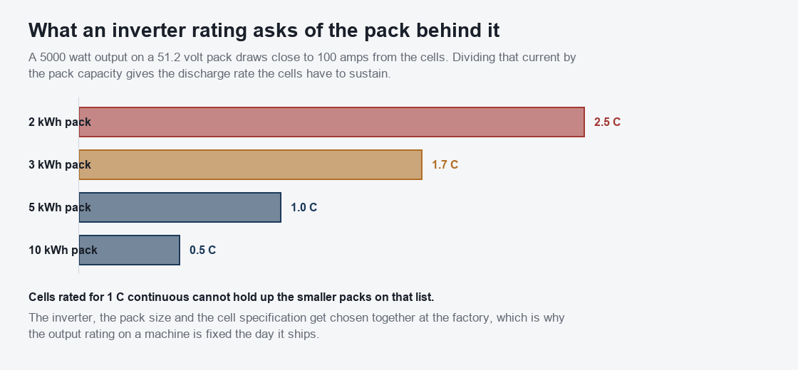
The weighting behind a published efficiency figure. Three quarters load carries 0.53 of it, which means the headline number describes one operating point far more than the other five.One output rating asks a completely different discharge rate of each pack size. Cells rated for 1 C continuous cannot hold up the smaller packs on the list.
Output rating sets a demand on the cells that owners rarely calculate. A 5000 watt output drawn from a 51.2 volt pack pulls close to 100 amps. Divide that current by the pack capacity and you have the discharge rate the cells must sustain. Small packs feel that arithmetic hardest. A 5000 watt inverter on a 2 kilowatt-hour pack asks 2.5 C of the cells, a rate few iron phosphate cells will hold continuously. On a 5 kilowatt-hour pack that output is 1 C. That’s why the inverter, the pack size and the cell specification get chosen together at the factory. A machine’s output rating is fixed the day it ships. There isn’t a way around that. No bigger inverter goes in later.
Solar ran into this problem twenty years ago and answered it with arithmetic. Under the California Energy Commission test protocol an inverter gets measured at six power levels: 10, 20, 30, 50, 75 and 100 percent of rated output. Every level runs at three DC input voltages, minimum, nominal and maximum. Eighteen measurements come out the far end. Those eighteen collapse into one number through fixed weights. The 75 percent point carries 0.53, more than everything else put together. Fifty percent carries 0.21 and thirty percent carries 0.12. The 10, 20 and 100 percent points carry 0.04, 0.05 and 0.05 between them. Apply that weighting to a residential string inverter with a 98.4 percent peak and the published figure lands between 97.5 and 97.8.
Portable power stations publish nothing of the sort. One peak figure appears on the page with no indication of where on the curve anybody took it. That gap bites harder here than on a roof, since the loads are smaller. Plug a 60 watt laptop into a 2000 watt inverter and the machine is working at 3 percent of rated output, below the lowest point the CEC protocol bothers to test. What happens down there goes unpublished by everyone. Anyone who wants the number can measure it. Run a known load, watch what leaves the pack, divide one by the other. An hour of that tells you more about a machine than its specification page does.
Watts, volt-amps and what a motor asks for
A resistive load keeps them identical. A kettle pulling 10 amps at 230 volts consumes 2300 watts and 2300 volt-amps, since current and voltage rise and fall together. Hang a motor on that socket and the two separate. Current lags voltage. Part of every cycle carries energy into the winding’s magnetic field and back out again without doing any work on the way. Real power is volts times amps times power factor. Apparent power drops the last term. Manufacturers quote whichever figure flatters. Victron’s MultiPlus-II 12/3000 carries two ratings on one line: 3000 VA and 2400 watts. The second assumes a power factor of 0.8. Load a 5000 VA machine to 5000 VA at that power factor and 4000 watts of actual work comes out of it.
Two specification sheets only compare when both quote one measurement. A page listing watts alone, with no power factor anywhere near it, has told you less than it appears to. Copeland puts locked rotor current at six or more times a compressor’s rated running amperage. It lasts 100 to 300 milliseconds, until the rotor starts turning. Trade sources elsewhere put the multiple between five and seven times full load amps. Read that against the surge column and the emphasis shifts. Duration turns out not to be the scarce thing. A fridge wants its inrush for a fifth of a second. Twenty seconds of surge headroom is generous past any use a domestic compressor will ever make of it. Machines fail on the multiple. A 150 watt fridge compressor at six times running current asks for roughly 900 watts, which almost any 2000 watt machine covers without noticing. A 900 watt well pump on that identical inverter asks for 5400. There is the arithmetic behind a power station that runs a fridge all summer and trips the instant a pump starts.
Frequency, voltage and heat
Synchronous speed follows straight from the supply. A four-pole motor turns at 1500 revolutions a minute on 50 hertz. That motor reaches 1800 on 60. Move a machine built for 60 hertz onto a 50 hertz supply and roughly 16.7 percent of its speed disappears. Output falls by a similar margin. The second effect does more damage and announces itself less. Flux in a motor or a transformer core tracks the volts-per-hertz ratio. A 460 volt motor designed for 60 hertz works out at 7.67 volts per hertz. Feed it 460 volts at 50 hertz and the ratio climbs to 9.2, a rise of 20 percent. The core moves toward saturation. Magnetising current climbs. Losses come out as heat.
Correcting it means dropping the voltage in proportion. A motor rated 230 volts at 60 hertz wants about 190 volts once the frequency falls to 50. An inverter switching between the two in firmware pays nothing at all for the change. Everything plugged into it does the paying. Five thousand watts leaves a 230 volt socket as 22 amps. That identical figure at 110 volts is 45 amps. Cable, connectors and the output stage all size themselves around current, never around watts. There is the reason a dual voltage machine tends to publish a lower ceiling on its 110 volt side. Long extension leads punish it twice over, since resistive loss in a cable follows the square of the current.
Continuous ratings get quoted at 25 degrees, which is a laboratory number more than a working one. Victron’s published MultiPlus 3 kVA specification lists 2400 watts at 25 degrees and 2200 at 40. Eight percent of the rating goes to nothing more interesting than a warm room. Portable machines do this too, with far less ventilation to work with. Most begin folding back their output somewhere around 45 to 50 degrees internal. A sealed case in direct sun reaches that on its own, before any load has been applied at all. Anyone sizing a machine for a summer job should read the continuous figure as a ceiling that travels downward as the day goes on.
The neutral question, and what certification covers
House wiring ties neutral to earth at one point. That bond is what gives a residual current device something to measure against. Current leaving on the live conductor should equal current returning on the neutral. Any difference means some of it found earth on the way. Most portable power stations leave the neutral floating. Neither output conductor holds a reference to earth, which changes what a fault even looks like. Touch one output conductor while standing on wet ground and no return path runs through you, since the other conductor connects to nothing you are in contact with. Seen that way, the floating arrangement is a safety feature. It also means a plug-in residual current device may never see the imbalance it exists to catch. Some tools with onboard protection refuse to run at all on a floating supply. Bonding plugs that tie neutral to earth get sold for exactly this situation. Several manufacturers forbid their use on the grounds that the machine’s own protection was designed around a floating output. Read the manual before buying one, since the answer varies by machine and getting it wrong takes protection away.
Certification covers construction. Performance stays outside its scope. IEC 62109-1 applies to power conversion equipment where a uniform level of safety is necessary. It addresses electric shock, energy, fire and mechanical hazards. Part 2 adds the requirements specific to DC to AC inverters, battery storage included. UL 1741 covers that ground in North America. It reaches inverters, converters, charge controllers and interconnection equipment for stand-alone or grid-connected systems. Neither standard promises the machine’ll run your fridge. They promise it won’t electrocute or ignite while trying.
Transfer time, and what it draws doing nothing
A power station standing in as backup has one specification that decides whether the trick works at all. When the mains drop, the machine has to notice and take over. Published transfer times cluster between 10 and 20 milliseconds. Measured behaviour across the category runs wider, from 10 out to 50. Facing that gap is the hold-up time of whatever was plugged in. An ATX desktop supply is designed to ride through at least 16 milliseconds of missing input. Most land between 15 and 25. Those two numbers only mean something read against each other. A machine transferring in 20 milliseconds, feeding a supply that gives up at 16, reboots the computer every time the mains flicker.
Dedicated hardware does better. An offline UPS transfers in around 8 milliseconds and a line-interactive design in about 5. Commercial units quote 2 to 6 and cap the specification at 10. That margin is the entire reason the dedicated product still exists. A power station covers a fridge or a router without trouble, since neither notices 30 milliseconds. A desktop on an older supply is the case that catches people out. Measured idle figures scatter far more than the marketing suggests. Reviewers put the Jackery Explorer 2000 V2 at roughly 17 watts and the Jackery 1500 near 15. EcoFlow’s Delta 2 lands around 14 to 16, the Delta 2 Max between 14 and 24, and the Delta 3 Max at about 27 with its inverter on and nothing drawing from it.
The Delta Pro shows where the loss actually lives. Inverter on and no load, it gives up 30 to 40 watts. Inverter off, that falls to 10 to 20. Most of the standby loss belongs to the inverter stage by itself, which turns the AC-off button into the most useful control on the panel for anybody leaving a machine switched on for days. A 25 watt difference held for a week is 4.2 kilowatt-hours, more than most portable packs hold in the first place. None of these figures appear on a specification page. Every one of them came from a reviewer with a meter. The number that decides whether a machine is still useful after three days in a van is the number nobody prints.
Choosing by what you run
One number decides the purchase ahead of all the others. What is the largest motor the machine has to start? Resistive loads draw what they say they’ll draw, and anything with a motor asks for several times its running figure during the first second. Answer that question honestly and the family chooses itself. The surge column separates the two constructions by a factor of two or three. Every other specification sits within a few percent. Portable owners running lights, laptops, fridges and power tools are served by high-frequency designs. That’s what portable machines carry. Anyone starting a deep well pump, a large compressor or a workshop saw is looking at iron whether they’d wanted a light machine or not.
Common questions
How can I tell which type of inverter a power station uses?
Look at mass and at the surge figure. A machine with a surge rating close to its continuous rating is a high-frequency design. Light weight confirms it. A surge rating two or three times the continuous figure, with the mass to match, means an iron transformer inside.
Can the inverter in a portable power station be upgraded?
No. The inverter, the pack and the cells are matched at the factory. Output rating belongs to the machine as a whole. No module inside it carries that number on its own. Buying for the largest load you expect is the only route.
Does surge rating matter for ordinary household loads?
It changes what the machine will start. Running is a separate question. A fridge, a pump or a compressor draws six or more times its running figure for the first 100 to 300 milliseconds, which lets a machine with a modest surge figure trip on an appliance its continuous rating covers easily.
Is a high-frequency inverter’s output waveform worse?
Both families produce a clean sine wave when the output stage is built for it. Control of that stage decides waveform quality, independently of the transformer. Both questions get answered separately.