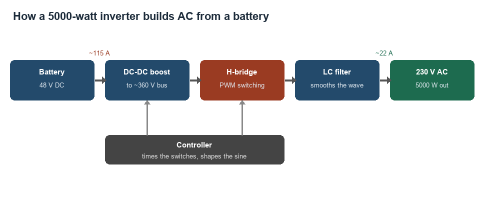
The chain inside a 5000-watt inverter, drawn as a block diagram. The battery 48-volt DC enters at the left. A boost stage lifts it to a bus near 360 volts. An H-bridge switches that DC into a wave. An LC filter smooths the wave into 230-volt AC at the right. A controller below times the switching. The figures are illustrative.
A 5000-watt inverter turns the direct current from a battery into the alternating current a home runs on. It takes in a steady 48 volts of DC and puts out a clean 230-volt AC wave at 5000 watts. The number 5000 is the power it can hold without strain, enough for a fridge, a microwave, and a row of tools at once. The work happens in a chain of stages inside the case. Each stage hands its output to the next. The battery’s low-voltage DC enters one end. A wall-socket AC wave leaves the other. This page follows that chain from the battery to the output. Each step in the chain has a clear, single job. The chain is short and the logic is plain.
The job sounds simple from the outside. A battery goes in. A wall socket comes out. The work inside is a careful chain of conversions. The inverter raises the voltage, switches it into a wave, and smooths that wave into a clean sine. A controller times every step. The chain turns 48 volts of quiet DC into 230 volts of working AC, thousands of times a second. The whole conversion runs in real time. No power is stored along the way.
The conversion chain, stage by stage
The power runs through four main stages. The first stage raises the battery voltage to a high DC level. The second stage switches that high DC into a rough AC wave. The third stage filters the rough wave into a smooth sine. The fourth part, the controller, times the switching across the whole chain. The four work together to turn DC into clean AC. Each stage is a known piece of power electronics. The parts have been proven over decades of use.
Each stage solves one piece of the problem. The battery voltage is too low for 230-volt AC on its own, so the first stage boosts it. The boosted DC is steady, so the second stage chops it into a wave. The chopped wave is rough, so the third stage smooths it. The order is fixed, since each stage needs the output of the one before it. A stage with nothing feeding it has nothing to do.
The stages cannot be skipped or reordered. The boost has to come before the bridge, since the bridge needs the high voltage to work from. The filter has to come after the bridge, since it cleans the bridge output. The controller sits across all of them, since it times the whole chain. The order is the logic of the design. Each stage earns its place by the one fact it fixes.
The chain is the same in a small inverter and a large one. A 5000-watt inverter runs the same four stages as a 300-watt one. The size shows in the parts. The plan stays the same. The bigger inverter uses bigger switches, a heavier transformer, and a larger heatsink to carry its 5000 watts. The working principle holds at every size. A bench inverter and a home unit share the same block diagram. Only the parts grow with the power.
Boosting the DC voltage
The first stage raises the battery voltage to a high DC level. A 230-volt AC wave reaches a peak near 325 volts. The DC behind it has to sit above that peak, near 360 to 400 volts. The 48 volts from the battery falls far below that level. The boost stage closes the gap. It lifts 48 volts of DC to a bus near 360 volts. That high bus is the raw material the rest of the inverter shapes. Every later stage works from it.
The boost works through a high-frequency transformer. The stage chops the 48-volt DC into a fast wave at tens of kilohertz. That fast wave passes through a small transformer that steps the voltage up. A rectifier then turns the stepped-up wave back into DC, now at the high bus voltage. The high frequency lets the transformer stay small and light. A fast wave carries its power through a small core with ease. The size of the magnetics drops as the frequency rises.
The high frequency is the trick that shrinks the parts. A higher switching frequency lets a smaller core carry the same power. At tens of kilohertz, a small ferrite core handles the full 5000 watts. The boost stage uses the fast wave to keep the inverter light. A fifty-hertz design would need a much larger iron core for the same power. The fast wave keeps a 5000-watt inverter down to a carry-able size.
The boosted DC is the foundation for the AC wave. It sits on a bank of capacitors that hold the high voltage steady. The capacitors smooth out the ripple from the boost stage. They also hand a burst of current to the next stage when a load jumps. The steady high-voltage bus is what the switching stage builds the AC from. The capacitor bank is the calm pool the bridge draws its power from. It steadies the voltage through every pulse.
The boost stage works in a loop. The controller measures the bus voltage many times a second. It widens or narrows the boost pulses to hold the bus near 360 volts. A jump in the load drops the bus for an instant. The loop catches the drop and pushes the bus back up. The bus stays steady for the H-bridge to draw on.
The boost stage carries the full power of the inverter. Every watt the socket delivers passes through the boost first. The transformer and switches in the boost are sized for the whole 5000 watts. A weak boost stage would cap the inverter below its rating. The boost sets the ceiling the rest of the chain works under. A strong boost is the base a strong inverter stands on.
The H-bridge that makes AC
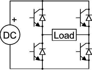
An H-bridge inverter circuit. A DC source sits at the left, marked DC with its positive terminal. Four transistor switches, each with an antiparallel diode, form the H, with the load across the middle. The switches close in alternating pairs to send current through the load first one way, then the other. The labels DC and Load are part of the drawing.
The high-voltage DC reaches the heart of the inverter, a circuit called the H-bridge. One reference describes the H-bridge as four switches, with a common use as an inverter that generates an AC wave across the load. The four switches sit in the shape of the letter H, with the load across the middle. The switches open and close in pairs to send current through the load. The H stands for the shape the four switches and the load draw on a page. The load hangs in the crossbar of the H.
The H-bridge reverses the current to make alternating current. One pair of switches closes. Current flows through the load one way. That pair opens and the other pair closes. The current flows the other way. The back-and-forth flow is alternating current by definition. The bridge flips the direction fifty or sixty times a second to set the frequency. The rhythm of the switching is the frequency the output holds. A faster flip would make a higher frequency.
On its own, the H-bridge makes a blocky wave. The switches send the full bus voltage one way, then the full voltage the other way. The controller shapes that blocky output through fast switching. It flips the switches on and off many times within each half of the wave, a method called pulse-width modulation. The width of each pulse traces the shape of a sine. A run of wide and narrow pulses adds up to a smooth curve. The filter that follows turns the pulses into a clean line.
The switches in a 5000-watt bridge carry heavy current. They are power semiconductors, either MOSFETs or IGBTs, built to switch high power fast. A 5000-watt inverter often runs several in parallel to share the load. The switches turn on and off thousands of times a second without wearing out. The whole AC wave is built by their timing. The switches are the muscle of the inverter. The controller is the timing behind the muscle.
The H-bridge is where the DC becomes AC. Every other stage serves this one. The boost stage feeds it the high voltage. The controller times its switches. The filter cleans up its output. The bridge itself is a handful of switches doing the core work of the inverter. The other stages feed it, time it, and clean up after it.
The switching inside the H-bridge is a fast, careful dance. Each switch turns fully on or fully off, never half-way, so it wastes little power itself. A switch snapped fully on carries the current with little heat of its own. The four switches work in two pairs. Only one pair conducts at a time. A short dead-time sits between one pair turning off and the other turning on. The dead-time stops both pairs from conducting at once. Two pairs on together would short the bus straight through the bridge. Inside each half of the AC wave, the controller pulses the conducting pair on and off thousands of times. Each pulse near the peak of the sine stays on longer than a pulse near the zero crossing. The string of pulses, wide then narrow then wide, traces the shape of the sine in time. An antiparallel diode across each switch gives the current a path when the switch turns off. A motor load pushes current back toward the bridge between pulses. The diodes carry that returning current safely. The bridge handles the power it sends out and the power a load sends back. Every pulse is timed to the microsecond by the controller. The speed of the switching sets how finely the pulses trace the curve. The switches in a 5000-watt bridge keep up with that speed at full current. The smooth sine at the output is the sum of thousands of these timed pulses, cleaned by the filter that follows. The H-bridge is simple in its parts and exact in its timing. The same dance runs fifty or sixty full cycles every second, without a pause. Nothing in the bridge moves except the flow of current through its switches. The bridge turns a steady voltage into a swinging one by timing alone.
Smoothing the wave
The H-bridge output carries the shape of a sine under a layer of fast switching ripple. The last stage is a filter of coils and capacitors that removes the ripple. The coil resists the fast jumps in current. The capacitor holds the voltage smooth between pulses. The filter passes the slow sine and blocks the fast switching noise. What leaves the filter is a clean 230-volt wave, ready for a wall socket. The filter is the last polish on the wave before it leaves the case. A device at the socket sees only the clean result.
The current a 5000-watt inverter moves
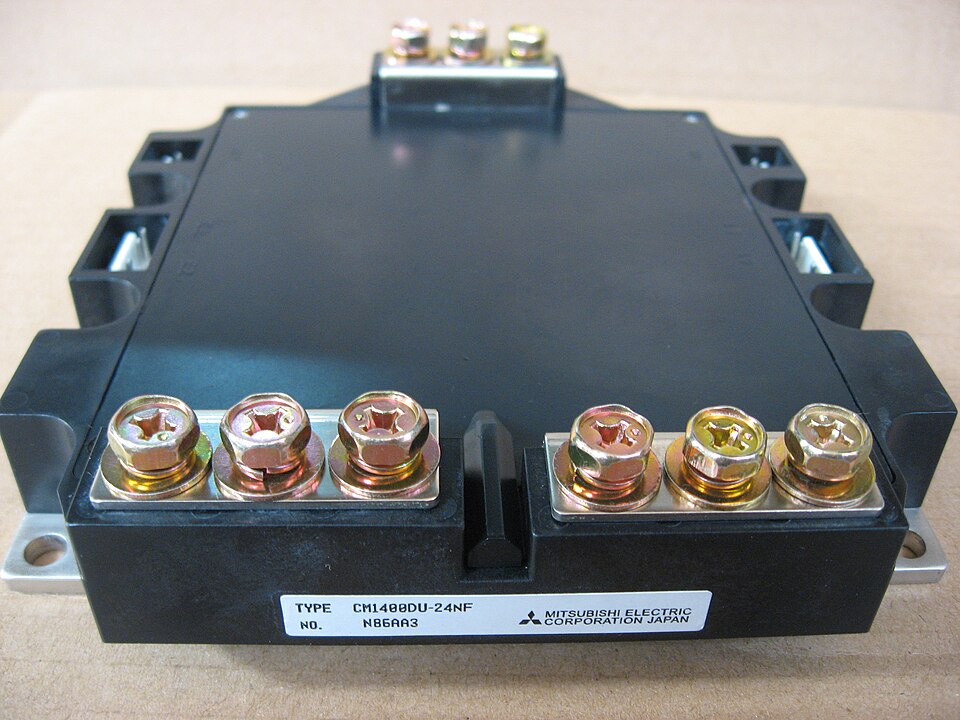
A real IGBT power module, the kind of fast high-current switch used in an inverter H-bridge. The bolted terminals carry the heavy current. The label reads the type CM1400DU-24NF, a Mitsubishi part. This module is an industrial-scale example, rated far above a portable inverter. A 5000-watt unit uses smaller switches of the same kind, either IGBTs or MOSFETs.
The power figure hides a large current. A 5000-watt load at 230 volts draws about 22 amps from the output. The same 5000 watts comes from the 48-volt battery, since power is voltage times current. At 48 volts, 5000 watts needs about 104 amps, before any losses. Real losses push the battery current near 115 amps at full load. The same watts move as a big current on the battery side. The low voltage there is the reason the current runs high.
The high battery current shapes the input side. The cables from the battery are thick, sized to carry 115 amps without heating. The connections are bolted, since a loose joint at that current heats fast. The battery itself has to supply 115 amps on demand. A 5000-watt inverter needs a battery and wiring built for the current. A thin cable on the battery side is the first part to fail under that load. The current sets the size of every wire it runs through. A 5000-watt inverter is a high-current machine on its battery side.
The output side carries a lighter current at a higher voltage. The 22 amps of 230-volt AC runs on wire no thicker than a household cord. The output socket and the AC wiring match a normal home circuit. The high voltage on the output is the reason the current there stays low. The table sets the input and output figures side by side. The output side looks like an ordinary wall circuit.
The current is why a 5000-watt inverter runs warm. Every amp through a switch or a wire leaves a little heat behind. At 115 amps on the input side, that heat adds up. The thick cables and big switches keep the heat per part low. The inverter carries its current with room to spare, so no single part runs hot. The current is shared and spread so the heat never piles up in one place. A margin in the parts keeps each one cool.
The power balances across the inverter. Close to 5000 watts enters from the battery. Close to 5000 watts leaves at the socket. The small gap between them is the heat the inverter sheds. The input runs 115 amps at 48 volts. The output runs 22 amps at 230 volts. The same power wears two faces, a high current at low voltage and a low current at high voltage. The inverter swaps current for voltage and keeps the power whole.
Key figures of a 5000-watt 48-volt inverter
Figure
Value
Battery input
48 V DC
Battery current at 5000 W
about 115 A
High-voltage DC bus
about 360 V
AC output
230 V
AC output current at 5000 W
about 22 A
Continuous power
5000 W
Heat at full load
250 to 500 W
Boost switching frequency
tens of kHz
Getting rid of the heat
No inverter is perfect, so some power turns to heat. A 5000-watt inverter loses a small share of the power in normal use, often five to ten percent. At full load, that loss is 250 to 500 watts of heat inside the case. The heat builds in the switches, the transformer, and the wiring. The inverter has to move that heat out to stay safe. The lost watts have to leave the case at the rate they build. A blocked vent traps the heat inside.
A heatsink and a fan carry the heat away. The power switches bolt to a metal heatsink that spreads their heat. A fan pushes air across the heatsink to carry the heat outside. The fan runs faster under a heavy load, since a heavy load makes more heat. The thermal design lets the inverter hold 5000 watts without overheating.
The heat is lightest at a gentle load. A 5000-watt inverter run at 1000 watts sheds far less heat than at full power. The fan idles or stays off at a light load. The cooling works hardest only when the load nears 5000 watts. An inverter sized above the everyday load runs cool through the better part of its work.
Heat sets a limit on the inverter. A sensor watches the temperature inside the case. The inverter pulls back its power if the heat climbs too high, to protect the parts. A clear path for air, away from walls and sun, lets the inverter run cool. The heat is the price of moving 5000 watts. The cooling keeps that heat in check.
The heat decides the size of the inverter’s body. A bigger heatsink and a stronger fan let a case hold more watts. The 5000-watt rating assumes the cooling can keep up at full load. A smaller case at the same rating would throttle back sooner under heat. The cooling and the power rating are tied together by the heat. A heavier case usually marks a higher real rating.
The controller that runs it all
A controller is the brain behind the stages. It is a small chip that times every switch in the inverter. It sets the boost stage to hold the bus voltage steady. It drives the H-bridge switches in the pattern that traces a sine. It runs the whole chain in step, thousands of times a second.
The controller also guards the inverter. It watches the voltage, the current, and the temperature at every stage. It shuts the inverter down on an overload, a short, or a low battery. It holds the output at a steady 230 volts through every change in the load. The controller turns a set of power parts into a safe, steady inverter. The controller is small in size and central to the design. It is the one part that knows the state of every stage.
The controller never rests from start to stop.
Misreadings of how it works
A few misreadings follow from the 5000-watt label. The first is forgetting the battery current. A 5000-watt inverter needs about 115 amps from a 48-volt battery. A battery or a cable too small for that current cannot feed the inverter. The output rating means little without an input built to match.
The second is ignoring the heat. A 5000-watt inverter sheds 250 to 500 watts of heat at full load. An inverter boxed in with no airflow overheats and pulls back its power. The cooling path is part of the working design. A clear space around the case lets the inverter hold its rating. A boxed-in inverter cannot keep its promise.
The third is expecting full power from any battery voltage. A 5000-watt inverter is built around one input voltage, often 48 volts. A lower battery voltage raises the current for the same power, past what the switches can carry. The inverter matches a battery of its rated voltage. The input voltage is fixed by the design.
The fourth is treating the wattage as the whole story. The 5000 watts is the steady power the inverter holds. The working chain behind it sets what the number means. A buyer who knows the chain reads the wattage with the input, the cooling, and the wave behind it. The number is the front of a design with real demands behind it. The chain behind the number is the real product.
The fifth is buying the inverter without the system around it. A 5000-watt inverter needs a battery that holds 115 amps, cables sized for the current, and a cool, open spot to sit. The inverter is one part of a working system. The 5000-watt figure is real only when the system behind it can feed and cool it. The working principle reaches past the case, into the wiring and the battery.
The sixth is judging the inverter by its size alone. A light, small inverter and a heavy one can share the same 5000-watt label. The heavier one often carries a bigger transformer and heatsink for hard use. The weight hints at the build behind the rating. A serious 5000-watt inverter has the mass of its cooling and its magnetics. The weight a buyer feels is the build behind the rating.
Common questions
How does a 5000W inverter convert DC to AC?
It runs the power through four stages. A boost stage lifts the 48-volt battery to a high DC bus near 360 volts. An H-bridge of four switches flips that DC into an AC wave. A filter smooths the wave into a clean 230-volt sine. A controller times every switch across the chain.
How much current does a 5000W inverter draw from the battery?
About 115 amps from a 48-volt battery at full load. The figure comes from 5000 watts divided by 48 volts, near 104 amps, plus the inverter’s own losses. The battery and the cables have to carry that current. A higher battery voltage lowers the current for the same power.
Why does a 5000W inverter need a heatsink and fan?
An inverter loses five to ten percent of the power as heat, near 250 to 500 watts at full load. The switches and the transformer make that heat in use. A heatsink spreads the heat. A fan carries it outside. Without the cooling, the inverter pulls back its power to protect its parts.
What is the H-bridge in an inverter?
The H-bridge is the circuit that makes the AC. It is four switches in the shape of an H, with the load across the middle. The switches close in alternating pairs. They send current through the load first one way, then the other. That back-and-forth flow is the alternating current.