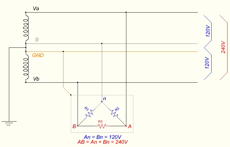
A schematic of the North American split-phase system. The center-tapped transformer gives 120 volts from each line to the center neutral, marked 120 V, and 240 volts across the two lines, marked 240 V. The equations An = Bn = 120 V and AB = 240 V show the split. The labels Va, Vb, GND, and R1 to R3 are the diagram own. A dual-voltage inverter built this way gives 110 and 220 on the same idea, at a slightly different nominal figure.
A dual-voltage inverter puts out two nominal voltages, near 110 volts and near 220 volts. The world runs on two main mains voltages, one near 110 and one near 220. Different regions settled on different figures long ago. A portable power station sold across regions offers both, so one unit serves a device from either world. The dual output is built into the inverter, set by how its transformer and control are wired. This page lays out the ways an inverter makes both voltages. The choice of method shapes the unit size, weight, and panel. A buyer rarely sees the method, only its two voltages at the sockets.
A dual-voltage inverter is the answer to a split world. It carries the two standards inside one box. A user crossing from a 110-volt country to a 220-volt one keeps the same power station. The output bends to the new region. The hardware that bends it is the subject of this page. The two standards live side by side inside the one case. A flick of a switch, or a wired-in tap, calls up one or the other. The two voltages wait inside for the one a device needs.
The two voltages do the same job at different levels. Each one delivers power to a device through a wall-style socket. A device carries its rated voltage on its label. The inverter has to meet that voltage. A dual-voltage unit holds both voltages ready. It matches the output to the device in front of it.
The implementation lives in the inverter’s output stage. The earlier stages build the AC wave at one working level. The output stage then sets that wave to 110 or 220 volts, through a transformer or the control. The way it sets the voltage decides whether the unit gives one voltage at a time or both at once. The sections below take each method in turn. Each method reaches the same two voltages by its own path.
The center-tapped transformer
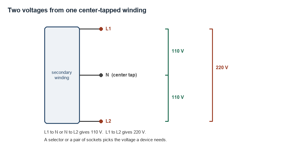
Two voltages from one center-tapped winding, drawn to show the taps. The winding two ends, marked L1 and L2, give 220 volts between them. The center tap, marked N, splits that span into 110 volts on each half. The center becomes the neutral and the two ends become the live lines. The figures are illustrative.
A direct way to two voltages is a center-tapped transformer. The transformer’s output winding has three connection points. The two ends carry the full voltage between them. A tap at the centre of the winding splits that voltage in half. One reference on split-phase power notes that either end to the centre has half the voltage of end to end. That single rule is the root of the whole method.
The numbers fall out of the tap. The full winding, end to end, gives 220 volts. Each half, an end to the centre, gives 110 volts. The centre point becomes the neutral. The two ends become the two live lines. One winding then carries 110 volts on each half and 220 volts across the whole. The same coil serves both voltages with no second winding. The economy of one winding is the charm of the center tap.
The center tap is a wire brought out from the middle of the winding. The winding is a coil of many turns. The tap connects at the turn halfway along. Each half of the coil holds half the turns, so each half makes half the voltage. The position of the tap sets the split. A tap at dead centre gives two equal halves of 110 volts. The transformer here is a heavy, low-frequency type with an iron core.
This layout gives both voltages at the same time. The neutral and one line make a 110-volt socket. The two lines make a 220-volt socket. Both sockets stay live together, fed by the one winding. A device of either voltage plugs in and runs, with no switch to set.
This is the split-phase system behind North American power. A home there takes 240 volts on two lines from the utility. The same two lines give 120 volts each to the ordinary sockets. A dual-voltage inverter built this way brings the same arrangement to a battery. The 120 and 240 of North America are the 110 and 220 of the inverter, at a slightly different nominal figure. The method holds the same whether the figures read 110 or 120. The split into two voltages is the constant across them.
The selectable tap
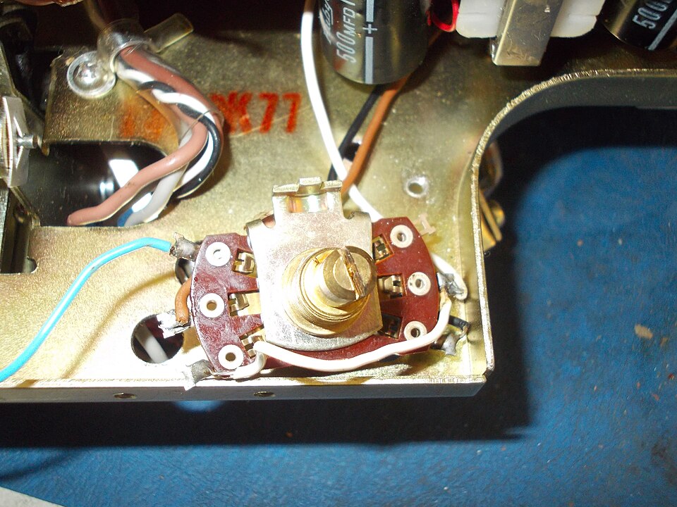
A real mains voltage selector switch inside a device, the brass rotary switch on the maroon board. The switch reconnects the transformer windings to set the voltage. The coloured wires route the winding taps to the switch. This selector sits on a device transformer input. An inverter uses the same kind of switch on its output to pick 110 or 220 volts.
A second method gives one voltage at a time, picked by a switch. The transformer carries taps for both 110 and 220 volts. A selector switch, or a relay the control drives, connects the output to one tap. The user sets the switch to the voltage the region needs. The inverter then puts out that one voltage. The tap holds its setting until a hand or a relay moves it.
This method suits a unit that moves between regions. A traveller sets the inverter to 110 in North America and to 220 in Europe. Only one voltage leaves the sockets at a time. The selector makes the unit a single-voltage inverter at whichever setting it holds. The switch carries a clear label, since the wrong setting can harm a device. The label by the switch names each setting in plain figures. A glance at the switch tells which voltage is live.
The software-set voltage
A third method sets the voltage in the control, with no tap to switch. A high-frequency inverter shapes its output by fast switching, so the controller can set the output to the level it is told. A setting in the firmware, or a button on the panel, picks 110 or 220 volts. The controller drives the switching to hold that level. The voltage becomes a number the software chooses, free of a mechanical tap. The same controller that shapes the wave also sets its height. A firmware figure fixes the output level.
The sockets and the plugs
The voltage is only half of fitting a device. The plug has to fit the socket as well. Each region built its own plug and socket shape over the years. A dual-voltage inverter has to offer sockets a regional plug will enter. The shape of the slots is a separate question from the voltage behind them. The slot shape and the live voltage are set up by separate parts of the unit.
Plug shapes run to a dozen common types around the world. The flat-blade Type A and Type B plugs serve North American sockets. The round-pin Type C and Type F plugs serve European sockets. The three-pin Type G plug serves the United Kingdom. A dual-voltage station picks the socket shapes for the markets it sells into.
Some units carry a set of region sockets. A panel might hold a North American socket, a European socket, and a universal one. A device plugs into the socket that fits its plug. The voltage behind each socket matches the region that socket serves. The user reads the panel for the right socket. The panel is the map a user reads each time.
The number of sockets shapes the panel. A small station might carry two or three sockets. A large one carries a row of them, some at 110 and some at 220. The panel groups the sockets by voltage, with each group marked. A user learns the panel once and reads it at a glance after.
A universal socket takes more than one plug shape. Its slots accept the pins of several regions at once. A universal socket on a 220-volt setting feeds a 220-volt device of any plug. A universal socket solves the plug shape on its own. The voltage behind it still has to match the device.
A universal socket is a clever piece of moulding. Its slots overlap the patterns of several plug types. A flat blade, a round pin, or an angled pin all find a path in. The contact behind the slots carries the voltage to whichever plug enters. One universal socket can replace a panel of region-specific ones.
The voltage of a region is a settled fact a user can look up before a trip. A quick search names the figure for any country. A traveller notes the figure for the destination and sets the inverter to it. The figure rarely changes, so the note holds for years. A user who checks once travels with the right setting. The local voltage is a fact to note before a trip.
The plug shape carries no voltage of its own. A plug fits a socket by its pins alone. The voltage comes from the inverter behind the socket. A travel adaptor changes the plug shape to fit a socket. It leaves the voltage for the inverter to set.
A dual-voltage unit reads best with the voltage marked on each socket. The mark tells the user the voltage before a plug goes in. Each socket carries the voltage printed beside it. Clear marking is the simplest guard against the wrong voltage. The label on the socket is the last check before the plug.
The marking on a socket does quiet work all day. A small printed figure, a colour, or a moulded number tells the voltage of that socket. A user glances at the mark and reads the voltage without a meter. The marking turns a panel of look-alike sockets into a clear set of choices. A good panel never leaves the voltage to memory. A marked socket answers the voltage question on its own. The mark is read in an instant, plug in hand.
Current at each voltage
The choice of voltage changes the current for the same power. Power is voltage times current, so the higher voltage carries a lower current for the same watts. A 1000-watt load draws about 9 amps at 110 volts. The same load draws about 4.5 amps at 220 volts, half as many. The watts stay the same across the two voltages. The lower the voltage, the higher the current for a fixed power. The two numbers trade off around the fixed wattage.
The lower current at 220 volts thins the wiring. A 220-volt circuit moves its power on a thinner wire than a 110-volt one. The sockets, the cords, and the output parts run cooler at the lower current. The 220-volt side of a dual unit carries its power with less copper. The same power costs more current at 110 volts. The copper in a cord is sized to the current it must carry. A thicker cord carries a higher current without heating.
The current weighs heaviest at high power. A 5000-watt inverter at 110 volts pushes about 45 amps through its output. That heavy current calls for thick output wiring. The same inverter at 220 volts pushes about 23 amps, near half as much. The lower current eases the wiring on the 220-volt side. The output wiring is sized for the worst-case current at each voltage. The gauge follows the amps the output can pass.
110-volt and 220-volt output, side by side
Property
110 V output
220 V output
Nominal range
110 to 120 V
220 to 240 V
Used in
North America, Japan
Europe, China, Africa
Current at 1000 W
about 9 A
about 4.5 A
Current at 5000 W
about 45 A
about 23 A
Output wire
thicker
thinner
Getting the voltage right
The voltage has to match the device, every time. A device carries its rated voltage on a label or a plate. The inverter output has to read the same figure as that label. The match of output to device is the whole point of a dual-voltage unit. A buyer checks the label, then sets or picks the matching output.
The device label is the one source of truth. It names the voltage the device needs, in plain figures. A reading of 120 V, or 220 to 240 V, or 100 to 240 V, tells the whole story. The user matches the inverter output to that range. The label is read once and the match is made.
The region a unit ships to often sets its default. A station arrives from the factory set to the voltage of its market. The default saves the first-time user a step. A careful user still checks the setting before the first heavy load. The factory setting is a starting point the user confirms. A new place is the time to check the setting.
Many devices today take a wide range of voltage on their own. A laptop charger marked 100 to 240 volts runs on either output. A phone charger does the same. These devices read the voltage and adjust inside. A wide-range device frees the user from the voltage question, on either setting of the inverter.
A single-voltage device needs its own voltage and nothing else. A device marked for one voltage runs only on the matching output. The label names that voltage, so the inverter has to supply it. The label settles the matter in a glance. A single-voltage device on the wrong output fails or burns.
Some inverters take the guesswork out with auto-detection or a fixed region build. An auto-sensing unit reads the load or the region and sets the voltage on its own. A region-fixed unit ships set to one voltage for its market. A clear panel and a careful read cover the rest. The voltage match is a habit a user builds with the unit.
A clear panel does much of the work for the user. It groups the sockets, marks the voltages, and shows the current setting. A glance at the panel answers the voltage question before a plug moves. The best panels leave nothing to memory or to guess. A user trusts a well-marked panel after the first read. The panel becomes second nature within a day of use.
A traveller’s kit shows the matching in action. A wide-range laptop and phone run on either output anywhere. A region-bound device, like some hair dryers, runs only at its home voltage. The traveller sets the inverter, or picks the socket, to match each device. The kit that crosses borders leans hardest on a dual-voltage output.
Matching the device to the output is the habit that makes a dual-voltage unit safe and useful. The match starts with the label on the device. Every mains device carries a rating somewhere on its body, on a moulded plate, a printed sticker, or the body of its plug. The rating names the voltage the device was built to take. The user reads that rating first, before any plug goes near a socket. The reading tells the user which output the device needs from the inverter. A device built for one figure runs safely only on the output set to that figure. Any other output brings it heat, smoke, or a quick death in a moment. The match is the guard against that result. The label puts it in plain sight. The modern world has eased the task a great deal. Laptops, phones, cameras, and their chargers now ship with a power supply that spans the globe, from a hundred volts up to two hundred and forty. A user with a bag of such gear barely thinks about the voltage at all. The supply reads the incoming voltage and adjusts on its own, on either setting of the inverter. The older and the simpler devices hold to one voltage still. A heater, a kettle, a hair dryer, or a motor names a single figure and asks the user to meet it. The habit of reading the label, once learned, takes a second at each plug. The reward is a device that runs on the power it was made for, in any country the user carries it to. The dual-voltage output makes that match possible. The user own read makes it happen. A power station that bends to either world is no use without that one read. The output and the read together close the loop.
Mistakes with dual-voltage output
A few mistakes follow from the two voltages. The first is plugging a 110-volt device into a 220-volt output. The device takes twice its rated voltage and can burn out in an instant. The fix is to read the device label and set the matching output. A moment’s check saves the device. The label is always there to read before the plug.
The second is leaving a unit on the wrong region setting. A selectable inverter set to 220 sends 220 to every socket. A 110-volt device on it meets twice its voltage. The user sets the selector to the region before the first plug goes in. The setting is the first thing to check in a new place. A new country is a new check of the selector.
The third is trusting the plug shape to guard the voltage. A plug that fits a socket says nothing about the voltage behind it. A travel adaptor makes any plug fit, voltage unseen. The fit of the plug and the match of the voltage are two separate checks. A plug that goes in is no proof of the right voltage. The voltage is checked at the panel before the plug.
The fourth is forgetting that some sockets carry 220 at all times. A split-phase unit keeps its 220-volt socket live beside the 110-volt ones. A user reaching for a 110-volt socket has to find the right one. The marking on each socket is the guide. A 220-volt socket in a row of 110s is a trap for a careless reach.
The fifth is ignoring the current on the 110-volt side. A heavy load at 110 volts draws a high current through the cord and the socket. A thin cord on that load runs warm. The 110-volt side asks for a cord sized to its current. The high current at 110 volts is the reason to watch the cord there.
The sixth is buying a separate voltage converter for a device. A dual-voltage inverter already supplies both voltages at the source. The right output, set or selected, gives the device its voltage with no extra box. A converter adds a part that the dual output makes needless. The inverter own output is the cleaner path.
The seventh is rigging two 110-volt sockets together for 220. A makeshift join of two outputs is no safe 220-volt source. The 220-volt output comes from the transformer, by design. A user takes 220 from the marked socket. A home-made link is never the way.
An eighth slip is forgetting the neutral on a split-phase unit. The 110-volt sockets draw from a line and the neutral together. A missing or loose neutral starves those sockets. The neutral is as much a part of the wiring as the two lines. A sound split-phase build treats the neutral with the same care. The neutral carries the return for every 110-volt socket. A loose neutral is a fault to rule out first.
The voltage match is one habit, learned once.
Common questions
How does an inverter make both 110V and 220V?
A common way is a center-tapped transformer. The full winding gives 220 volts end to end. A tap at the centre gives 110 volts from each end. The two ends become the live lines and the centre becomes the neutral. Other inverters use a selector switch or a software setting to pick one voltage at a time.
Can a 110V device run on a 220V output?
No. A 110-volt device on a 220-volt output takes twice its rated voltage and can burn out. The device label names its voltage. The inverter output has to match that figure. A wide-range device marked 100 to 240 volts runs on either output, since it adjusts inside.
What is split-phase output?
Split-phase output comes from a center-tapped transformer. It gives 240 volts across two lines and 120 volts from each line to a center neutral. North American power works this way. A dual-voltage inverter built on split-phase offers both voltages from one winding at the same time.
Why does 220V use a thinner wire than 110V?
Power is voltage times current, so a higher voltage carries a lower current for the same watts. A 1000-watt load draws about 9 amps at 110 volts and about 4.5 amps at 220 volts. The lower current at 220 volts needs less copper. The thinner wire is a result of the higher voltage.