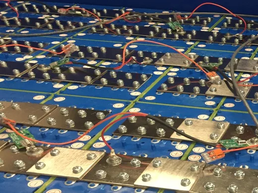
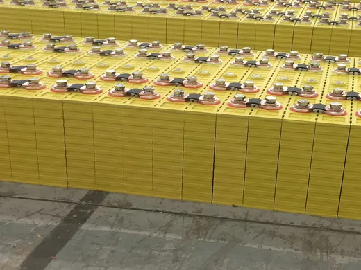
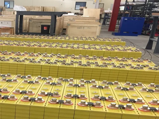
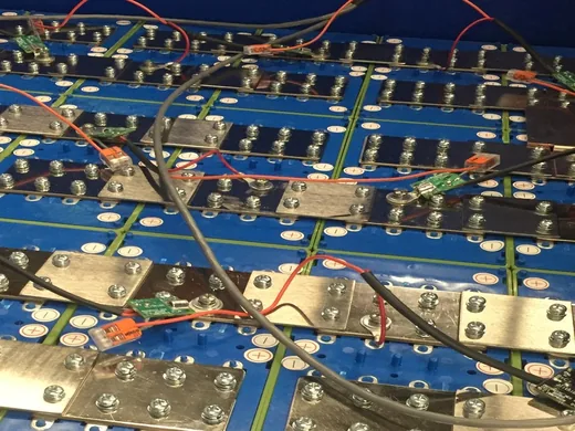
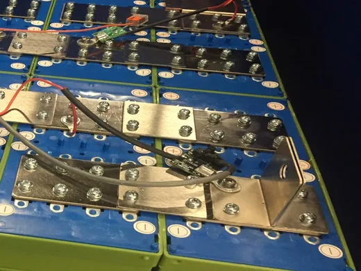
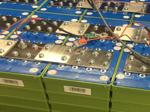
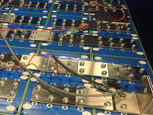
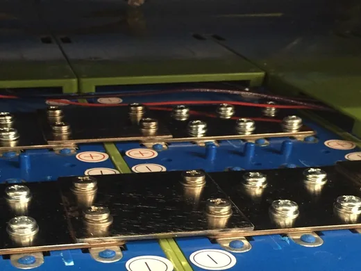
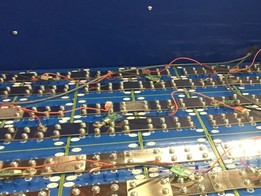
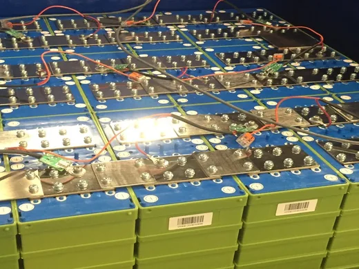
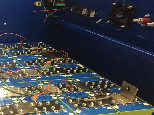
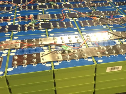
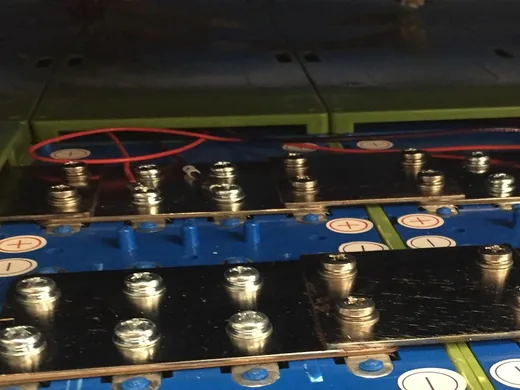
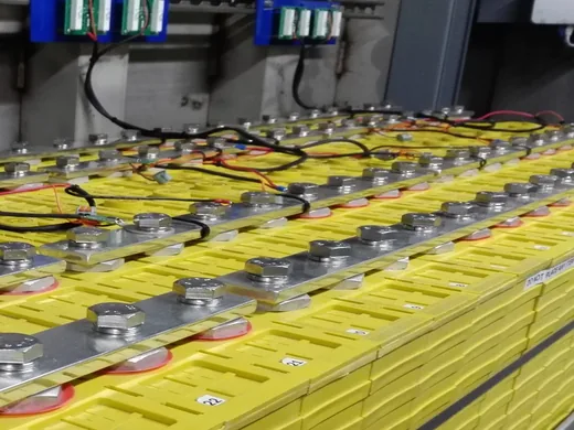
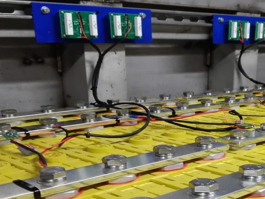
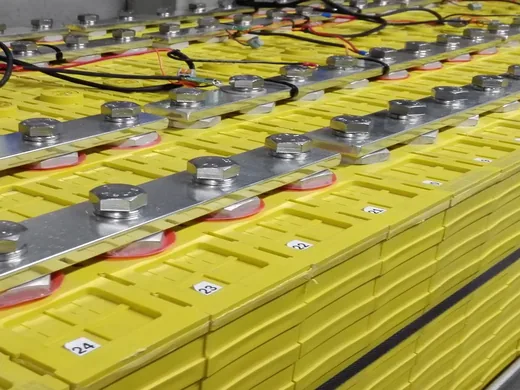
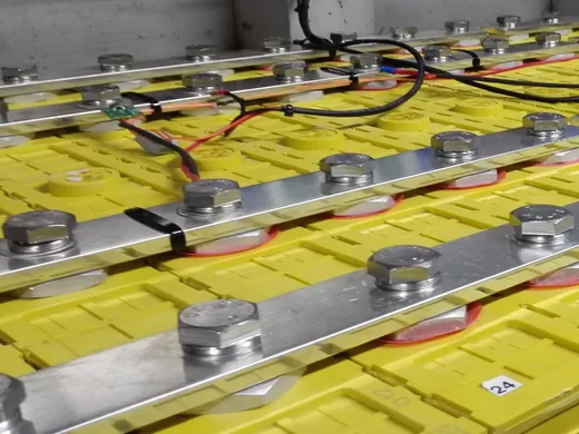
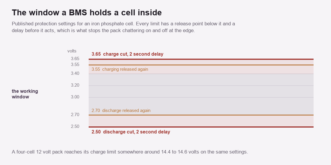
Published protection settings for an iron phosphate cell. Each limit carries a release point on the other side of it, which is what stops a pack chattering on and off at the edge.
Take the voltage limits first, since they carry the heaviest load. A published setting for an iron phosphate cell puts the charge cut at 3.65 volts. The board releases charging again once the cell falls back to 3.55. Discharge cuts at 2.50 volts and releases at 2.70. Both actions carry a delay of about two seconds. Three separate mechanisms hide inside those two sentences. First comes the limit itself. It comes from the cell datasheet. No board designer picks that number. No setting screen should offer to move it. The release point follows. The gap between limit and release is hysteresis. Take the hysteresis away and a pack sitting exactly at 3.65 volts would cut, recover, cut and recover several times a second, wearing the switch and confusing everything downstream of it. Third is the delay. Wait two seconds and a brief spike travelling through the pack passes without consequence. A genuine condition still gets caught long before it does harm. Every threshold on that protection list carries all three parts, which is why a specification quoting only the limit has told you a third of the story. Pack-level numbers follow from the cell-level ones by arithmetic. Four iron phosphate cells in series reach the charge limit somewhere around 14.4 to 14.6 volts, which is why a 12 volt charger for this chemistry looks wrong to anybody expecting lead-acid figures. Sixteen cells in series put that limit near 58 volts. The board watches individual cells throughout, since a string sitting at a correct total can still hold one cell above its own limit and another below. What the board does at a limit varies with how far the design has been thought through. Opening an internal switch is the blunt response. Either a relay or a MOSFET in the current path performs it. Asking the connected equipment to reduce or stop is the graceful one. It needs a data link, plus equipment willing to listen. Some designs work on the environment. Heaters or fans bring a cell back inside its window with nothing disconnected at all. A fourth response exists in firmware alone, where the board slows a processor or drops a clock to shed heat without touching the pack at all.
Temperature limits follow that pattern with different consequences. A charge window that closes below freezing is a hard limit. Below that point the board refuses charging outright. Current limits carry the shortest delays of all. A dead short pulls hundreds of amps within microseconds. The hardware that catches it acts before any software has looked. None of these numbers appear on a machine’s outside. They live in the board’s firmware. The only route to them is the manual or an app.
Published protection settings for an iron phosphate cell. The release column is what prevents repeated tripping at the limit.
Condition
Limit
Release
Delay
Cell over-voltage
3.65 V
3.55 V
about 2 s
Cell under-voltage
2.50 V
2.70 V
about 2 s
Pack charge limit, 4 cells
14.4 to 14.6 V
follows the cells
as above
Charge below freezing
refused outright
on warming
immediate
Short circuit
hardware detection
manual or timed
microseconds
The switch, the wiring and the measurement
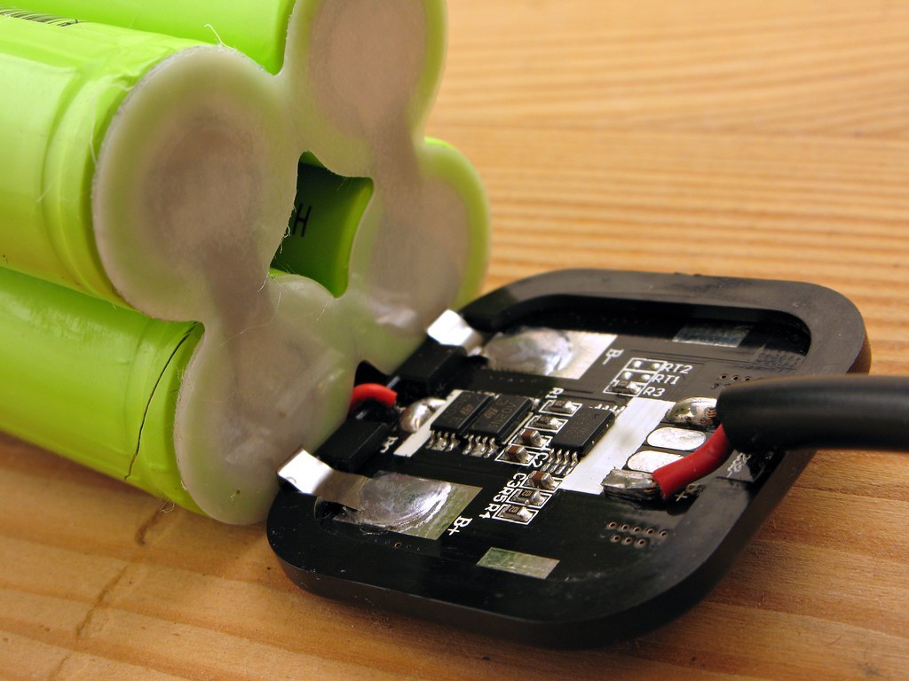
A protection board welded onto a cell pack. The silkscreen marks B-, P- and the RT pads for thermistors, which is the measurement chain this page is about. Photo by Phil Gradwell, CC BY-SA 2.0.
Protection needs something that’ll open. Small packs use MOSFETs in the current path. Larger packs use a contactor, a relay built for the current a big pack delivers. Either way the board’s decisions arrive as a mechanical or solid-state disconnection. A switch in the main path costs something to have. MOSFETs drop a little voltage and turn it into heat. Hold a contactor closed and it draws current for as long as it stays there. Neither cost is large. Both are permanent.
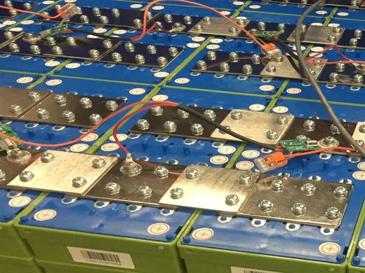
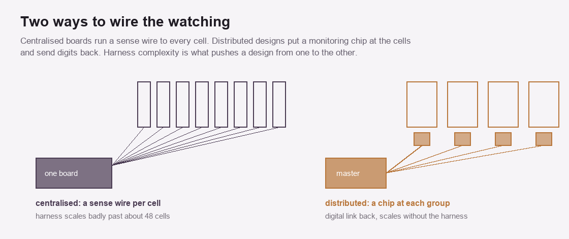
Two ways of getting cell voltages back to a controller. The harness is what pushes a design from the first arrangement to the second.
A centralised board runs a wire to every cell and does all the reading in one place. Design and manufacture stay simple, which is why the arrangement dominates small packs. Its harness is what limits it. Complexity climbs with cell count and gets awkward somewhere past 48 cells. Long analogue sense wires pick up electrical noise on the way back.
A distributed design puts a monitoring chip at each cell or group and sends digits back to a controller over one communication link. Scalability improves and fault tolerance improves. You pay for it in more electronics in more places. Modular designs sit between the two, with a handful of controllers each handling a subset of cells. Portable machines below a few kilowatt-hours almost all use the centralised arrangement, since a 16-cell pack sits well inside where a harness stays manageable.
Voltage measurement is the easy part. It’s the part every board gets right. Modern front-end chips resolve millivolts. Consistency between channels is what counts here. Absolute precision matters less. Current measurement runs through a shunt or a Hall sensor. Integrating that current over time is how the board tracks charge in and out. The accuracy of a state of charge calculation rests on that integration alone for most of the pack’s range. Between 20 and 80 percent charge an iron phosphate cell moves from about 3.26 volts to 3.35. Ninety millivolts covers sixty percent of the capacity, which leaves voltage almost nothing to correct a drifting count with.
Cell-to-cell differences are the third measurement. They count for more than the absolute figures do. Moving charge out of a full cell into a low one at 1 to 10 amps is the job of active balancing across multiple series cells. Between 85 and 95 percent of what leaves arrives. A passive board burns that excess off through a resistor at 30 to 100 milliamps. At that rate a 10 amp-hour imbalance takes a hundred hours to close.
Talking to the rest of the machine
A management board inside a portable machine reports to the inverter and the charger over a data link, usually CAN or a serial bus. Charge current gets requested, never assumed. The charger obeys a limit the board sends it. Three numbers travel over CAN for coordination between the BMS and the inverter: a charge voltage limit, a charge current limit, and a discharge current limit. On better packs all three get recalculated from cell voltage, charge state and temperature as conditions move. The inverter switches off its own charge algorithm once those arrive and the battery’s figures take over. New limits land in about a second. The control loop needs another second or two to act on it. Without the link an inverter sees terminal voltage and nothing else, which leaves a hard cut-out as its only move. Detection precedes disconnection. That’s where boards differ. Give a board self diagnosis on its own faults and it can tell a genuine cell fault from a broken sense wire, which stops a wiring problem from shutting the machine down.
Not every fault deserves an identical response. Thirty millivolts out of line is information. Nobody needs waking up for it. A cell above its limit is an action. Three separate numbers make up tiered handling of abnormal BMS alarms on a single cell over-voltage event. Charging stops at 3.65 volts a cell. Then it waits two seconds. Charging resumes when the cell falls back to 3.55. A single threshold would chatter the charge circuit on and off across that gap all afternoon. A board that treats every reading as an emergency teaches its owner to ignore the panel. Logs matter more than alarms in the end, since they’re what a technician reads. A board that records what it saw, with a timestamp, turns a mystery shutdown into a readable event.
Cold, and the first millisecond
Below freezing an iron phosphate cell stops accepting charge properly. Lithium arriving at the anode plates onto the surface as metal in place of working its way into the graphite. Plated metal never comes back. Capacity drops permanently. The deposits can grow into dendrites, which raises the risk of an internal short. The board’s answer is blunt. A low-temperature charge cutoff disables charging outright once the sensors read below zero. Published guidance for the 0 to 5 degree band limits charge current to 0.1C, a tenth of the rated capacity expressed in amps. On a 100 amp-hour pack that works out at 10 amps, closer to a trickle than to charging.
Discharge is where the window turns asymmetric. A pack refusing to charge at minus five will still deliver current at that temperature, with less capacity and a lower voltage under load. Owners read the refusal as a fault, since the machine plainly still works. It is working exactly as designed. Anything used outdoors through winter wants charging indoors, or charging after a run long enough for the cells to have warmed themselves. Connect an inverter to a pack and its DC input capacitors travel from zero to full pack voltage almost at once. Nothing limits current during that instant except cable resistance and whatever the internals contribute.
The figures run larger than most people expect. Epoch Batteries puts initial inrush at 800 to 2500 amps on a 12 volt system in a low-resistance installation. A 24 volt system sees several hundred to over a thousand. At 48 volts the number reaches several thousand amps across the inverter bank. A board watching for over-current sees that and opens. The machine appears to fail at the moment of connection, every single time. Raising the threshold to stop the nuisance trip pushes the problem into the MOSFETs, which then absorb the full spike on every startup for the working life of the product. Contactors carry their own failure mode here and can weld closed.
A precharge resistor is the fix. Current runs through it first and fills the capacitors slowly. Only then does the main path close. Published values run 6 ohms at 50 watts for 12 volt systems with a 5 to 15 second hold, 22 ohms at 100 watts for 48 volt systems with a 15 to 30 second hold. None of this shows on a sealed portable machine, where the precharge lives inside and is sized around the one inverter it was built for. There is a real difference between a factory-matched unit and a pack somebody wired to an inverter by hand.
Two speeds of over-current, and an idle balancer
Over-current and a dead short are separate conditions with separate hardware behind them. A short-circuit comparator watches the voltage across the sense shunt continuously and fires the gate drivers in under 200 microseconds, with some implementations quoted below 7. Ordinary over-current protection takes 1 to 5 milliseconds, which is ample for a load that has simply grown too large. Thresholds separate too. A short-circuit trip typically comes in at five to ten times the rated continuous current. On a board rated 100 amps continuous that puts the threshold between 500 and 1000. A spanner dropped across the terminals crosses it in microseconds and the board opens before the busbar has time to heat. What happens afterwards separates them further. A short-circuit trip latches the board off. It stays off until the fault clears and somebody resets it, or until a configured timeout expires. An over-current trip usually clears itself once the load drops away. Balancing looks broken to anybody watching a display. The current reads zero for hours at a stretch. Nothing about that is a fault.
Orion’s manual states the rule plainly: balancing runs only when the board is powered in charge mode. Beyond that, one cell has to cross a start-balancing voltage before the algorithm begins at all. The board then finds the lowest cell and loads every cell sitting more than the allowed delta above it, with 10 millivolts the recommended setting. It pauses regularly to let voltages settle and re-reads the spread before carrying on. Above 50 degrees on the heatsink it stops entirely. The reason lives in the curve. Below roughly 3.4 volts an iron phosphate cell tells you almost nothing about its charge, which is that flat plateau doing its work again. Two cells both reading 3.28 volts might be 20 percent apart. Only near the top does voltage separate far enough to identify which cell genuinely holds more. A board balancing down in the flat region would be shuffling charge on the strength of measurement noise. Standing idle is correct behaviour. It also explains why a pack never charged to full never gets balanced.
What it costs while nothing happens
A board never stops drawing current. Monitoring channels take 30 to 100 microamps each. Add communication and the figure climbs, since a smart board running Bluetooth, RS485 or UART draws milliamps. Sleep mode answers that. With no current flowing, no communication and no wake signal, a board can drop below 800 microamps. Some designs go under 50, which is the figure worth hunting for on anything that spends months in a cupboard. Put those two through a year and the difference shows. A steady 800 microamps removes about 7 amp-hours over twelve months. A 1 kilowatt-hour pack at 51.2 volts holds roughly 20 amp-hours. A third of that can disappear into a board doing nothing. At 50 microamps the yearly total falls under half an amp-hour.
The arithmetic decides whether a stored machine survives. Unoptimised sleep states are reported to cost 2 to 5 percent of capacity a month. Six months of that is close to a third of the pack. Fall under the under-voltage threshold in storage and the machine may refuse to wake at all. Recharging every three to six months keeps cell voltage above the point where the board latches off. It is the one piece of routine care an iron phosphate machine genuinely asks for. Counting coulombs drifts. Every measurement carries a small offset. Integrate an offset over hours and it becomes a large error. A board needs a reference point to reset against. Full charge is the obvious one. Once the pack reaches its charge cut and current tapers away, the board knows where it stands and writes 100 percent into the count. The bottom of the curve gives the second reference, since below roughly 20 percent an iron phosphate cell finally starts to move in voltage. That knee is sharp enough to locate.
Between those two points the board flies on dead reckoning. A machine living between 40 and 70 percent for months, never filled and never emptied, gets no opportunity to correct itself. The percentage on its display drifts quietly the whole while. Charging to full occasionally has nothing to do with the cells at all. It gives the board somewhere to take a fix.
Certificates and the protocol that never was
Three marks turn up on iron phosphate machines and they cover different ground. UN 38.3 is about transport. It tests altitude, vibration, shock and thermal cycling so a pack can legally travel by air, sea or road. Nothing in it describes how the pack behaves in service. UL 1973 is the stationary storage standard and it does reach the board. Its method assumes a failure will happen and asks what contains it. The BMS has to meet functional safety requirements, with UL 991 covering the hardware and UL 1998 covering the software. IEC 62619 is the international counterpart and comes at that territory from a long-term performance angle. A machine carrying UN 38.3 alone has been certified safe to ship. That is a smaller claim than it looks.
Closed-loop communication rests on something flimsier than most buyers imagine. Pylontech published its CAN message format around 2015 to let inverter partners talk to its batteries. No IEEE specification sat behind it. No certification body, no compliance testing, no conformance suite. It was internal documentation, shared. Enough batteries adopted it that the format turned into a de facto standard by weight of numbers. Other manufacturers reverse engineered the message structure and copied it, message IDs and byte positions included. Inverter makers added support because too many packs on the market spoke it to ignore. Reverse engineering leaves gaps. One battery and inverter pairing runs faultlessly for years. Another pairing, both sides claiming the identical protocol, throws intermittent communication errors that nobody can pin down. Closed-system inverters remove the question altogether. They refuse to talk to anything except their maker’s own packs. No amount of configuration changes that.
A sealed portable machine sidesteps the whole problem. Its board and its inverter were written to work together and never have to negotiate with a stranger. That is worth remembering when comparing an integrated machine against a pack and an inverter bought separately.
What it will not do
A management board protects cells from conditions. It does nothing about cells that were poorly matched when the pack was built. It can’t recover capacity that ageing has taken. It won’t make a small pack deliver a large current, since its limits come from the cells. It has no opinion about how the machine gets used, beyond refusing the operations that would damage it. Owners sometimes read a good board as a guarantee of pack quality. Those two are unrelated. A good board on mediocre cells protects mediocre cells accurately, reports their decline honestly, and disconnects them at the right moment. The cells still decide what the machine can do.
Common questions
What does a BMS actually protect against?
Over-charge, over-discharge, over-current in both directions, over and under-voltage, over and under-temperature, and short circuit. Each condition has a limit, a release point on the other side of the limit, and a delay before the board acts. Quote only the limit and you have given a third of the setting.
Why does my pack cut off before it reads empty?
Because the board watches individual cells and the display watches the pack. One cell reaching 2.50 volts stops discharge for the whole string, whatever the total reads. That behaviour points at cells drifting apart, with the board doing its job.
Can BMS settings be changed?
Some boards expose settings over an app or a serial link. Raising a protection limit past what the cell datasheet allows removes the protection. It doesn’t improve the machine. The useful adjustments are things like alarm points and reporting.
Does a bigger BMS give more power?
No. The board’s current rating has to match the pack and the inverter. Raising it alone changes nothing, since the cells set what the pack can deliver. A board rated well above the cells never becomes the limiting part.