A power station runs on two parts that have to agree with each other. Watched over by its BMS, the battery holds the energy and guards the cells. Drawing on that energy, the inverter turns it into the AC a load needs. Each works to its own brief. Coordination is the running agreement that keeps the two briefs from pulling apart, struck and re-struck many times a second.
Each part knows something the other cannot see. Down at cell level, the BMS reads the voltage, the temperature, the charge left inside every cell. Out at the sockets, the inverter reads the load, the watts a user pulls at this moment. Between them they cover the whole machine. Put the two views together, and the pack can run safely right at the edge of what it can do.
Their goals line up nearly all the time. The BMS wants safe cells. The inverter wants steady power for the load. Drain a pack too hard or charge it too fast, and both goals fall into danger at once. Moment by moment, the two parts settle the terms between them to keep that from happening. A pack pushed past either goal pays for it in lost life or a dropped load.
The signals the BMS sends
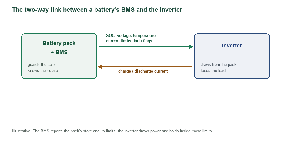
The two-way link between a battery’s BMS and the inverter, drawn as a flow. The BMS reports the pack’s state and its limits: state of charge, voltage, temperature, the live current limits, and any fault flag. The inverter draws charge and discharge current from the pack. It holds that current inside the limits the BMS sets. The figure is illustrative.
In a handful of numbers, the BMS says all it needs to. State of charge, pack voltage, temperature, a fault flag for trouble: each one tells the inverter a single thing about the battery. None is hard to read. The inverter takes them in a fixed order, the fault flag first of all. Reading the fault first keeps the inverter from acting on a stale limit in an emergency. Speed is what counts in the instant when a fault appears.
Two of those numbers carry the heaviest weight. They work as limits, a step beyond a plain reading. The BMS sets a ceiling on charge current and a ceiling on discharge current, the safe maximum the cells will take in or give out at this instant. Neither ceiling stays fixed. A cold pack, or a nearly full one, carries lower ceilings than a warm, half-full one. Each change in the cells brings a new ceiling.
State of charge sets the broad plan for the day. The headline reads plainly. Near full, ease the charge. Near empty, wind the load down. Hours of runtime, the figure a user watches, ride on that same percent. Every other number gets weighed against it. A pack at eighty percent and one at twenty call for different handling. A full pack carries that load with room to spare.
One flag outranks all the rest. Should a cell cross a hard limit, the BMS raises a fault at once. To the inverter, that flag is a plain, absolute stop order. Every other number waits until the fault clears. Until a human or the BMS lifts it, the stop holds.
What the inverter does with each number
Numbers alone do nothing. Each one earns its place by changing how the inverter behaves. A current limit caps the watts the inverter may pull. A high temperature pulls that cap lower still. A low state of charge tells the inverter the end is near. No number reaches the inverter without a job to do. Each one maps to a single lever the inverter can pull.
Reading the current limit is the heart of it. The inverter checks the watts it pulls against the ceiling the BMS sets. Stay under, and it carries on at full tilt. Approach the ceiling, and it holds the load where it is. A managed approach to the ceiling beats a hard stop against it every time.
Voltage and charge guide the slower decisions. From the pack voltage the inverter judges how close charging is to done. From the state of charge it judges how much runtime is left. Neither calls for a sudden move. The slow numbers carry the plan. The fast ones handle the emergencies. A spike in load meets an answer in milliseconds.
Current limits, moment by moment
Of all the numbers, the current limits change the fastest. Many times a second, the BMS works out afresh how much the cells can safely give or take. Temperature feeds into the sum. State of charge feeds into it. The health of the cells feeds into it. Out comes a single figure in amps, fresh each instant. A figure a second old is old enough to matter on a hard load. The fast refresh keeps the inverter’s draw inside a limit that is always current.
A discharge limit guards the giving side. Pull more than the cells can spare, and their voltage starts to sag. To head that off, the BMS names the safe maximum before any strain shows. Under that line the inverter keeps the load. A sag the user never sees is a sag the limit caught in time.
A charge limit guards the taking side. Push more current than the cells can absorb, and lithium plates where it should not. To keep that from starting, the BMS caps the charge current. On its way to full the charger holds to the cap. The cap is there because plating never undoes itself once it starts. Held clear of it, the cells keep their capacity far into their life.
Both limits read in amps, or in C-rate. At one C the pack will give or take its full capacity in an hour. At half a C it takes two. Whatever the unit, the inverter reads the figure and shapes its current to fit. The same rule reads a fifty-amp pack and a two-hundred-amp one alike.
The closed-loop link
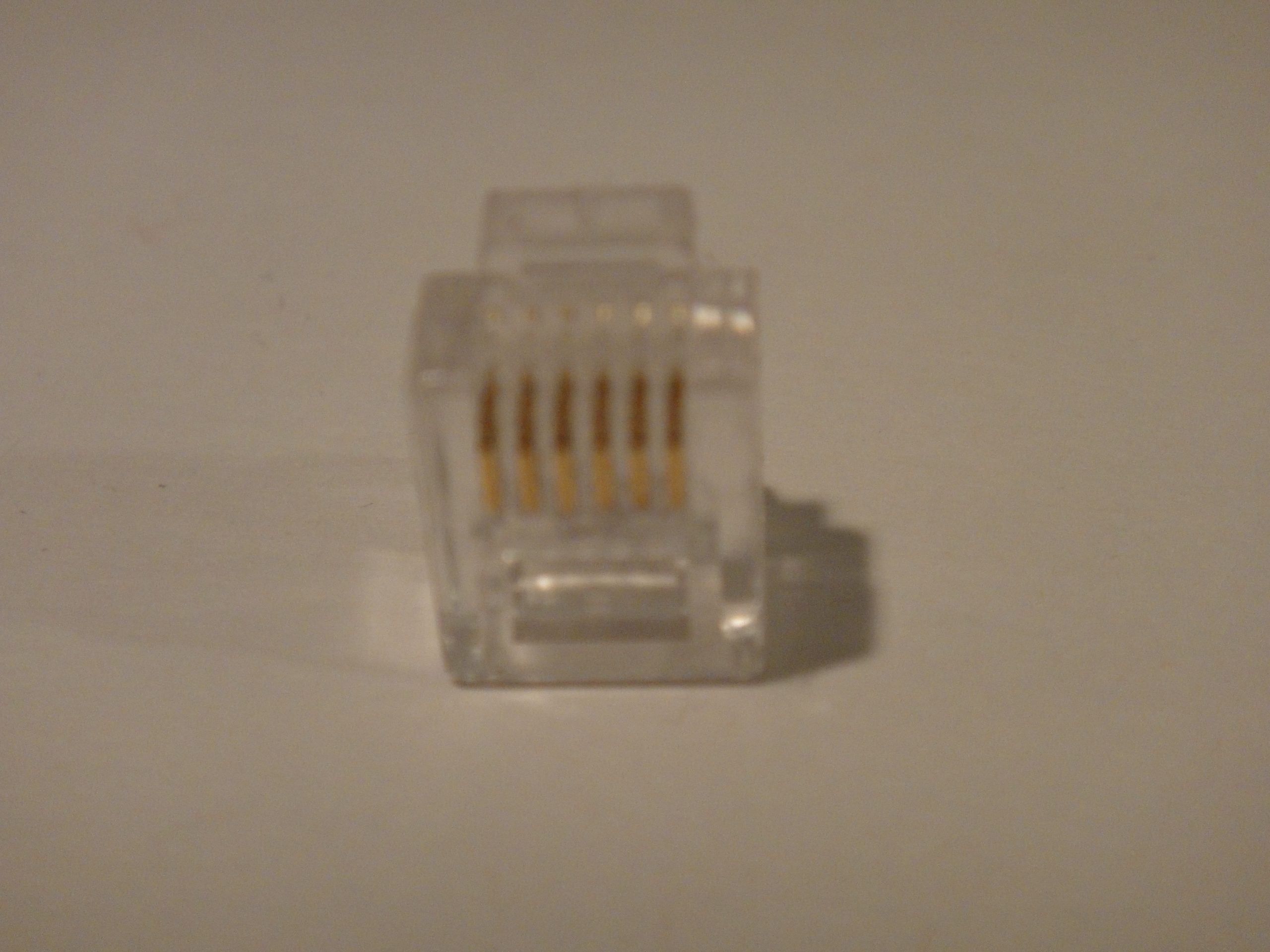
A real 8P8C modular plug, the RJ45-style connector that often carries the comms link between a battery and an inverter. The gold pins are its contacts. A CAN bus or RS485 cable runs from the battery’s BMS to the inverter through a connector like this. The same plug joins a computer to a network. It stands for the kind of link the comms ride on.
A closed-loop system wires the two parts into a conversation. Between the battery and the inverter runs a data cable. Across it the numbers flow many times a second. The link runs two ways. The BMS reports its state. The inverter acts on it. Nothing on either side runs on a guess.
Nearly all of these conversations ride on CAN bus. Born in the car industry, the protocol suits parts that must talk in real time. Messages cross in milliseconds, each one checked for errors as it arrives. A corrupted frame is caught and dropped before it misleads anyone. Share the CAN language between a battery and an inverter, and the two trade their numbers cleanly. The error check is built into every frame they send.
Only a thin cable carries the link. Often ending in an RJ45 plug, a single network-style cable runs the whole conversation between the two boxes. The plug is cheap. The wire is common. Familiar hardware does an unfamiliar job. The same plug serves a laptop and a battery bank.
Precision is what closed-loop coordination buys. Working from the cells’ real state, the inverter knows the exact limits of the moment. Charging tapers on the BMS’s word. The load winds down on the BMS’s word. Every move traces back to a measured number.
The protocols they speak
A shared language is what makes the link work. Raw numbers alone get the two parts nowhere. They need an agreed format, a protocol both sides read the same way. CAN bus is the common choice. RS485 carries a share of the links as well. A few makers run a protocol of their own on top of the same wires.
Each protocol fixes how a message looks. A frame holds an identifier, a few bytes of data, a check for errors. Into one frame the BMS packs the state of charge, into another the current limits. By the same rulebook the inverter unpacks them. A byte out of place would read as the wrong number. Both sides hold hard to one fixed format.
Matching protocols is the catch in the closed loop. A battery and an inverter that speak the same dialect link up at once. A pair that does not stays mute, dropping back to voltage alone. This is exactly why compatibility lists exist. Checking that list before buying saves a mute link later.
Coordination on voltage alone
An open-loop system skips the cable entirely. Between the battery and the inverter, no data passes at all. The inverter watches one thing on its own: the pack voltage at its terminals. From that single clue it judges the battery’s whole state. One voltage stands in for every number a wired link would carry.
Voltage tells only a coarse story. The inverter sets fixed thresholds in advance. Charge runs until the voltage reaches one figure. The load stops when it falls to another. Those thresholds are guesses at the pack’s real limits. They never move. They take no account of temperature or the age of the cells. A cold morning throws the same threshold off by a wide margin.
The two parts still work without a cable. A pure resistive load, a gentle charge, a pack well within its limits all run fine on voltage alone. The simple cases never test the limits of the coarse method. The cost of open-loop shows only when the pack is pushed to a corner. Those corners are exactly where a comms link earns its place.
Closed-loop and open-loop coordination compared
Aspect
Closed-loop
Open-loop
The link
a data cable (CAN bus or RS485)
none; voltage only
What the inverter knows
SOC, voltage, temperature, live current limits, faults
the pack voltage alone
The limits used
the BMS’s real-time limits
fixed voltage thresholds, set in advance
Near a limit
a graceful taper of power
full power until a hard cutoff
Tracks temperature and age
yes
no
Pairing
a matched, compatible battery and inverter
any battery and inverter
Easing the load near a limit
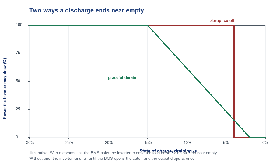
Two ways a discharge can end near empty, drawn as the power the inverter may draw against the falling state of charge. The green line is a graceful derate: with a comms link, the BMS lowers the limit early and the load winds down for a soft stop. The red line is an abrupt cutoff: with no link, the inverter runs at full power until the BMS opens its switch and the output drops at once. The figures are illustrative.
Near the bottom of the charge, the clearest payoff of coordination shows up. A pack running low cannot safely give the full power it gave when full. Through the last stretch of charge, the BMS lowers the discharge limit a little at a time, holding the cells back from the floor. Reading each new limit, the inverter follows it down, trimming the power it pulls to match. What a user sees is a soft landing. The figure on the screen slides toward zero, the available power easing off with it, a clear warning in plain sight. There is time to finish a task, to save a file, to wrap up before the output stops. The pack settles to empty without a single cell forced past the line that would harm it. The whole sequence runs quietly, the way good engineering tends to run. None of it happens by luck. The taper rides on the live discharge limit the BMS sends down the link, refreshed many times a second against the real state of the cells. Every step of the taper is a small message sent and a small action taken, dozens of them before the pack is empty. Each message runs a few bytes, sent and answered faster than an eye can blink. Through the whole descent the pack and the inverter stay in lockstep. No human hand touches the controls. The whole exchange plays out below the level a person could follow. The cells finish the discharge as evenly as they began it, none run down harder than the rest. A user notices none of the machinery, only that the power held and then bowed out cleanly. A battery that can warn its inverter, paired with an inverter that listens, turns a hard wall into a gentle slope. That gentle slope, beyond any single feature, is what coordination is for.
Heat draws the same kind of response. On a hot day a hard-working pack climbs in temperature. With the heat rising, the BMS pulls the current limit down. The inverter eases the load. A few hundred watts given up for a minute beats a shutdown that drops the whole load. The lights stay on through a moment that would otherwise drop them.
Full charge earns the gentle treatment too. A pack near the top cannot take full current safely. As the cell voltage climbs, the BMS pulls the charge current down. Backing off on cue, the charger tops the cells up slowly for the last few percent.
Every bit of this asks for the closed-loop link. Fine, moment-by-moment shaping of power runs on the live limits the BMS sends. An inverter cannot taper toward a limit it never hears about. Without the conversation, the gentle slope is plainly not on offer.
A graceful taper near a limit is the signature of two parts that talk. The power eases off. The work in hand gets a moment to finish. No cell feels the jolt of a sudden stop.
The hard cutoff
Some faults leave no room at all for a gentle taper. A dead short, a cell racing past its safe voltage, a temperature spike past the danger line: each one calls for an instant stop. In a moment the BMS opens its main switch and cuts the battery off. With no warning, the inverter loses its power source. Its output drops at once. When nothing slower will do, a hard cutoff is what protects the cells. That protection comes at a price: the abrupt loss of power, a load dropped mid-task. A whole day of coordination works to keep things from ever reaching that point.
Shaping the charge
As much as discharging, charging leans on coordination. A lithium pack wants a careful charge: full current at first, a steady taper near the top, a clean stop at full. The shape the cells want is what the BMS knows. Following it is the job of the charger inside the inverter.
Temperature reshapes a charge on the spot. A cold pack cannot take a fast charge safely. Down in the cold the BMS holds the charge current low. A warmer pack earns a higher current back. A pack left to warm regains its full charge current.
Cell balancing rides along with the charge. Near full, the BMS sets to evening out the cells. For that work, the charge has to hold near the top a while. The BMS asks the charger to wait. The charger holds the voltage steady.
A full pack has to stop taking charge. Past one hundred percent, more current does nothing but stress the cells. Calling the charge complete, the BMS drops the charge limit to zero. A full pack asks for no more current. The inverter offers none.
Many batteries, one voice
Big systems stack many batteries together. Feeding a single inverter, a rack of modules can hold a dozen packs, each with a BMS of its own. A dozen voices at once is more than the inverter can hear. The batteries have to speak as one. One voice is all the inverter can follow.
One BMS takes the lead. Linked in a chain, the modules choose one of their number to speak for the group. It gathers the state of every module, sums the currents, averages the rest, and reports a single virtual battery to the inverter.
What the inverter sees is one clean set of numbers. To it, the whole rack looks like a single large battery: one state of charge, one current limit, one fault line. The lead BMS builds that figure, packing the whole crowd of modules into it. Ten modules or one read the same to the inverter. Adding a module changes nothing the inverter can see.
A solar system in the real world
Picture an off-grid cabin running on solar. Panels feed a hybrid inverter. The inverter feeds the house and a wall of batteries. A comms cable ties the battery BMS to the inverter. Every part of the day leans on the link between them. That same link guides the charge and the discharge alike.
Morning brings the panels to life. As the sun climbs, the inverter pushes charge into the pack. The BMS watches the current and the cell voltages the whole time. Near full, the BMS calls for a taper. The inverter eases the charge to keep any cell from overfilling. By noon a homeowner sees a full battery and a quiet evening of power ahead.
Evening hands the load back to the battery. After dark, the house draws from the pack alone. The BMS counts it down. Low on charge, the BMS trims the discharge limit. The inverter sheds the heaviest loads first. The same routine repeats every sunny day, untouched by any hand.
Inside a single power station
A portable power station folds both parts into one box.
Sharing a circuit board, sometimes a single chip, the BMS and the inverter sit inches apart. No cable runs between them, no protocol to match. Over short traces the two talk at the speed of the silicon. Closed-loop by design, the pairing has the inverter built to read the BMS beside it. Nothing about it falls to a user to set up or check. Baked in from the factory, the graceful tapers and clean shutdowns are the work of one designer who drew both halves. Inside one sealed box the cable is short, the match guaranteed, the handshake quick. A buyer pairs nothing and matches nothing.
When the two fall out of step
Poor coordination shows itself in rough edges. Smooth tapers go missing. Power drops without warning. The pack hits its limits with a jolt.
Worst of all is an over-discharge. Blind to the real limit, an inverter can pull a low pack too hard. Down go the cells, below their safe floor, before the cutoff catches them. Drained that deep again and again, a pack loses life fast. A handful of deep discharges can cut its lifespan short.
Nuisance trips come from the other direction. Ignoring a derate request, an inverter keeps pulling full power into a limit. No gentle option is left to the BMS. It trips the hard cutoff. A load dies mid-task, lost to a fault the inverter would not help head off.
Behind much of this lie mismatched parts. A battery and an inverter from different makers may not share a protocol, or may read the same numbers differently. Falling back to open-loop, voltage alone, they lose the fine coordination a matched pair would have. Buy the pair as a pair, and the coordination comes built in.
Reading the spec and trusting the edges
Whether the two will talk shows on the spec sheet. A compatibility list names the inverters a battery can run closed-loop, by make and model. A mention of CAN bus or RS485 points to a comms link on board. A battery tied to one inverter brand carries that brand’s name on the page. Reading those lines before buying settles the match in advance. A name absent from the list is a warning in plain sight.
A portable power station hides all of it. Settled inside the box, the pairing has the BMS and inverter matched at the factory. A buyer reads the runtime, the surge rating, the clean low-battery behaviour. Each is a fruit of coordination. The plumbing behind it stays out of sight. A spec sheet rarely spells the coordination out. The behaviour near full and near empty tells what the sheet leaves unsaid.
Coordination is the quiet handshake that makes a battery and an inverter one system. Two things meet at that link: what the BMS knows about the cells, and the power the inverter sends to the load. A fast, two-way link between them lets each do its job. Neither half forces the other past a limit. The calm at the edges of a charge is that coordination, made plain.
Frequently asked questions
What does a BMS tell an inverter?
A BMS reports the battery’s state of charge, its voltage, its temperature, and a fault flag for trouble. It also sends two limits: the highest current the cells will take in, and the highest they will give out, safely at that moment. The inverter reads all of this and works inside the limits.
What is closed-loop communication?
Closed-loop communication is a two-way data link between the battery’s BMS and the inverter. The BMS sends its live state and limits across a cable, often over CAN bus. The inverter acts on those numbers in real time. Charging and discharging follow the cells’ real condition. They never run on a fixed guess.
What happens if the BMS and inverter do not communicate?
Without a data link, the inverter runs open-loop on the pack voltage alone. It sets fixed thresholds for charge and cutoff, guesses at the real limits. The pairing covers everyday use. Its weak spots sit at the edges: the graceful tapers and the deep-discharge protection both fade near full, near empty, and in the cold.
Do I need a matching battery and inverter?
For closed-loop coordination, yes. The battery and the inverter have to share a protocol and a compatibility list. A matched pair trades live limits and tapers power gracefully. A mismatched pair falls back to voltage-only control. That coarser control still covers ordinary use. A portable power station settles the match inside the box, with nothing for a user to pair.