A hundred watts names a size class. Buy a rigid monocrystalline panel of that rating and a fairly predictable object arrives. Roughly a metre long, two thirds of a metre wide, three centimetres thick in its aluminium frame, weighing about 7.5 kilograms. Typical published dimensions run 1000 by 665 by 30 millimetres. Module efficiency for that footprint lands near 18 percent on older designs and past 20 on current ones. Check the efficiency claim against the footprint before believing it. One metre by 0.665 is 0.665 square metres. Test light delivers 1,000 watts to every square metre. That aperture receives 665 watts. A hundred watts out of it is 15 percent. Datasheets in this class often print 18 percent alongside those exact dimensions, which is cell efficiency standing where module efficiency belongs. The arithmetic takes ten seconds and catches the substitution every time.
Buyers reach for this class because of what it feeds. Anything smaller struggles to keep pace with a machine’s own standby drain across a cloudy week, and anything larger stops fitting behind a seat. One panel of this size suits a small station, a van fridge, a boat light circuit, a shed. Two of them suit a mid-size machine. Manufacturers standardised on it early. Mounts, cables, connectors and stands are all sized around it.
Portable versions of the identical rating look nothing alike. A folding hundred watt panel drops the glass and the frame. Published weights for laminated folding panels run 2.2 to 5 kilograms. Folded dimensions cluster near 600 by 565 by 55 millimetres, unfolding to something like 1130 by 595. Wattage matches the rigid module. Almost nothing else does. Both objects deliver a hundred watts under laboratory light. What separates them is how they survive being owned, and how much of a car boot they claim while doing it. Cell format complicates the picture for anyone reading a modern datasheet. Wafer sizes have grown through 166 millimetres, 182 and 210, known in the trade as M6, M10 and G12. Run the arithmetic on the first of those. A 166 millimetre square is 0.0276 square metres. At test irradiance of 1,000 watts per square metre and 22 percent efficiency it makes about 6 watts. Thirty-six such cells add up to a 216 watt module. Small panels either stay on older 156 millimetre cells or cut larger ones down. Two panels of identical rating can end up with very different cell counts.
Thirty-six cells and the twelve volt habit
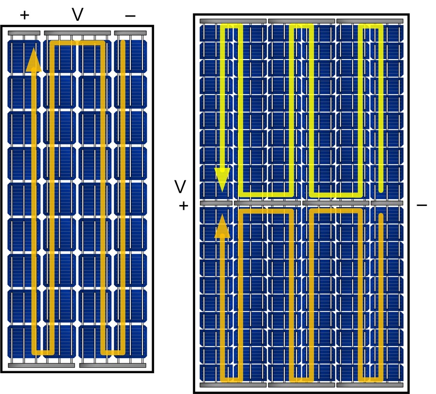
Two ways to lay out the identical cell area. On the left one series string snakes through full cells. On the right the cells are halved and the module runs as two parallel strings, which halves the current in each. Diagram by César Domínguez, CC BY-SA 4.0.
Silicon cells hand over about half a volt each. Panel voltage is a count. That half volt is the one number in the panel that size cannot change.
Open-circuit voltage comes out of a logarithm. The standard expression is Voc equal to nkT over q, multiplied by the natural log of the light-generated current divided by the saturation current. Two things live in that line. The first is kT over q, the thermal voltage, worth about 26 millivolts at room temperature. The second is the saturation current. It measures how fast carriers recombine before collection.
Silicon has a bandgap of 1.12 electronvolts, which on a naive reading promises about 1.1 volts a cell. Commercial cells deliver around 690 millivolts. Laboratory records reach 764. The missing 400 millivolts is called the bandgap-voltage offset. It is recombination, sitting inside that logarithm as the saturation current. A better cell recombines less. Voc rises a few millivolts at a time.
Two consequences follow for anyone holding a panel. Cell area cannot raise voltage, since a bigger cell collects more photons and produces more current at the identical half volt. Voltage has to come from counting cells in series. A 36-cell module lands near 22 volts open-circuit. A 60-cell rooftop module lands near 38. Thirty-six cells in series is the traditional answer for this class, chosen decades ago to charge a twelve volt lead-acid battery through a simple controller with margin left for heat. Work backwards from the footprint and the cell size falls out. Thirty-six cells sharing 0.665 square metres leaves about 0.018 each, gaps included. That points at a 125 millimetre pseudo-square, five inches across the flats, cut from a round ingot with its corners chamfered. Three watts a cell at that size and the module lands near its hundred. The 36-cell convention grew up around that format. It survives in small panels long after large modules moved to 166 millimetres and beyond.
Numbers from a representative 36-cell hundred watt module show what that produces. Open-circuit voltage 22.6 volts. Voltage at maximum power 18.4 volts. Current at maximum power 5.43 amps. Short-circuit current 5.87 amps. Multiply the two maximum-power figures and 100 watts comes back out. Those four numbers hide a fifth that nobody prints. Divide rated power by the product of open-circuit voltage and short-circuit current. For this module that is 100 divided by 22.6 times 5.87, which comes to 0.754. That figure is the fill factor. It measures how square the current-voltage curve is. A perfect cell would hold full current right up to full voltage and score 1.0. Real cells lose the corner to series resistance in the fingers, ribbons and contacts, and to shunt paths across the junction. Good crystalline modules land between 0.75 and 0.82. Anything much under 0.70 in this class announces resistance where none should be. The calculation takes ten seconds on any datasheet.
Read the four together and the working envelope appears. Open-circuit is the highest voltage the panel ever presents, reached with nothing connected. Short-circuit is the highest current, reached with the terminals bridged. Neither extreme delivers power. The useful point sits inside both. A controller spends its life hunting for it.
Shading is where a series string turns dangerous, which is the reason those diodes exist at all. Cells in series carry one current. Cover one cell and it can no longer supply that current. The other thirty-five then drive it backwards into reverse bias. The shaded cell then dissipates the power the rest are producing, as heat, in a patch of silicon under a sheet of glass. That is a hot spot. It can crack a cell or scorch a backsheet.
Bypass diodes come with the cell count. Standard practice puts one across every 18 to 24 cells, giving two of them in a nominal 12 volt module and three in a 24 volt one. Their effect on voltage is dramatic when they conduct. A 36-cell module presenting about 22 volts open-circuit drops to roughly 11 with one diode engaged. Half the string has been bridged out.
An owner who sees a panel reading half its expected voltage in dappled light is usually watching a diode do its job. Cell layout has moved on since the 36-cell convention. Halving each cell and running the module as two parallel strings cuts the current in each string. Resistive loss follows the square of current. Half the current leaves a quarter of the loss in the ribbons and fingers carrying it. The cells themselves are unchanged. All of the gain comes from the wiring between them. Modules built that way carry a higher cell count at a similar voltage. The arithmetic that matters to an owner stays identical: volts times amps at the maximum power point.
The layers between the glass and the cable
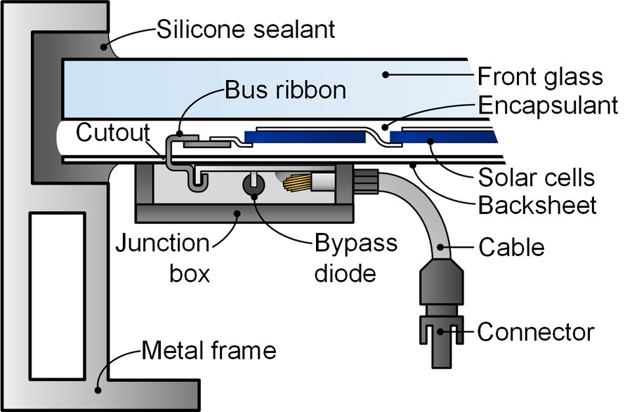
A cut through the edge of a framed module. Every layer named here has a job, and most panel failures in the field are a failure of one of them rather than of the silicon. Diagram by César Domínguez, CC BY-SA 4.0.
A framed panel is a sandwich under glass. Tempered front glass takes the weather and the impacts. Encapsulant, usually a cured sheet of ethylene vinyl acetate, holds the cells in optical contact with that glass and keeps moisture off them. Cells sit in the middle, joined by flat tinned copper ribbons soldered across their front and rear busbars. A backsheet closes the underside. An aluminium frame grips the edges through a bead of silicone sealant. A junction box hangs off the back. Inside it the bus ribbons terminate, bypass diodes bridge groups of cells, and two cables leave with connectors moulded on. Bypass diodes matter more than their size suggests. A shaded cell would otherwise sit as a resistance in the series string and heat up. The diode routes current around its group.
Portable folding panels rearrange that stack. Glass gives way to a laminate, commonly a fluoropolymer film over the cells, bonded to a flexible or segmented backing and sewn into a fabric case. Frames disappear altogether. The junction box shrinks or moves into the case. Cables terminate in whatever connector the machine expects. Each substitution buys portability and spends something else. Laminate scratches where glass would not. A sewn hinge flexes where an aluminium frame would hold. Neither choice is wrong. They answer different questions about where the panel spends its life. Sealing decides how long the box on the back survives. Junction boxes carry an ingress rating, commonly IP65, IP67 or IP68. A quality module built for 25 years outdoors uses one of the better two. Water that finds its way in has two routes to cause trouble. It corrodes the ribbon terminations, raising resistance at the one point in the panel where every amp passes. It also provides a leakage path from live conductors to the earthed aluminium frame, which a wet leakage current test exists to catch. Neither shows up as an obvious symptom. Both show up as a panel quietly producing less than its neighbours.
Rigid or folding at the identical wattage
Weight decides most purchases in this class. A rigid hundred watt module runs about 7.5 kilograms. Folding laminates of that rating run 2.2 to 5. Carrying one to a campsite is a different act from carrying the other. Packed size follows. A rigid panel is a metre-long rectangle that cannot be made smaller. A folding panel collapses to something near 600 by 565 millimetres and 55 thick, roughly a large briefcase. Vehicle owners with a roof rack often prefer the rigid module for exactly the reason campers avoid it: it can be bolted down and left. Durability runs the other way. Glass under an aluminium frame survives decades of weather because that construction has been refined for decades. A laminate over a sewn backing survives being folded, dropped and stuffed behind a seat. Ask either to do the other job and it disappoints.
Laminate chemistry separates the good folding panels from the cheap ones. Fluoropolymer films, sold as ETFE, hold their transmission under years of ultraviolet. Cheaper polyester laminates yellow and haze on a shorter clock. A hazed front surface costs output every hour the panel is used afterwards. The difference rarely appears on a specification sheet in this class. Find the material name before buying. Warranty length tells that story from another direction. A framed glass module in this class carries 12 years on materials and 25 on power output. Folding panels commonly carry one to three years on everything. That gap is the manufacturers’ own estimate of which construction lasts. Deployment differs as well. A folding panel arrives with a stand sewn into the case, which sets its own angle in seconds. A rigid module needs a mount, a bracket or a wall. The folding version also lets an owner chase the sun through the day. A bolted panel stays where it was fixed.
A representative 36-cell hundred watt monocrystalline module, and the folding equivalent
Figure
Rigid framed module
Folding laminate
Rated power
100 W at Standard Test Conditions
100 W at Standard Test Conditions
Open-circuit voltage
22.6 V
18 to 24 V typical
Voltage at maximum power
18.4 V
18 to 20 V typical
Current at maximum power
5.43 A
about 5.5 A
Short-circuit current
5.87 A
about 5.9 A
Dimensions
1000 x 665 x 30 mm
about 1130 x 595 unfolded
Packed size
fixed, 1000 x 665 mm
about 600 x 565 x 55 mm
Weight
about 7.5 kg
2.2 to 5 kg
Power tolerance
0 to +3 W
varies by maker
Warranty
12 years materials, 25 years linear output
commonly 1 to 3 years
What one panel returns in a day
Rated watts describe an instant under laboratory light. A day’s harvest needs the local sun figure and a system factor. Multiply the rating by the site’s peak sun hours for the theoretical number. Take between 60 and 75 percent of that for angle, temperature, dirt, cable and controller losses combined. Run that for a hundred watt panel at four and a half peak sun hours. The theoretical day is 450 watt-hours. The realistic day lands between 270 and 340. Winter in a cloudy country can halve that again. A bright cold spring morning can beat it. Those numbers set expectations for what a single panel supports. Three hundred watt-hours refills a small station overnight. It runs a 45 watt van fridge for most of a day. A two kilowatt-hour machine needs a week of good weather from one panel this size. Cloud changes the picture in a way the daily average hides. Current from a silicon cell tracks irradiance almost proportionally. Under 200 watts per square metre of overcast light a panel produces close to a fifth of its rated output. Voltage holds up far better, dropping only slightly. That combination is why a panel still charges under cloud where a naive reading would expect nothing. Low irradiance performance is a named item in the IEC 61215 qualification sequence for exactly that reason. Put those watt-hours against real loads and the panel’s place becomes clear. A 25 watt router draws 600 watt-hours a day if it never sleeps, which one panel of this size cannot cover in winter. A 15 watt phone charger run for three hours takes 45. A 45 watt van fridge cycling at roughly a third duty draws about 360 watt-hours across 24 hours, which one good summer day of a hundred watt panel almost matches. Seasonal spread does more damage than any of those averages suggest. A site averaging four and a half peak sun hours across the year may see six in June and two in December. Sizing a panel against the annual average leaves an owner short for a third of the year. Sizing against December means carrying more panel than needed all summer. Most portable owners carry a second panel for winter. Recorded output from a hundred watt panel outdoors comes in a quarter to a third under nameplate on clear days.
Matching a panel to a machine
Two figures decide compatibility, and only one of them is the wattage. Open-circuit voltage has to stay under the machine’s maximum input voltage at the coldest temperature the panel will see. Charging current has to stay under the machine’s maximum input current. A 22.6 volt panel suits almost anything with a solar input. Machines commonly accept 11 to 60 volts, sometimes wider, which leaves generous headroom for one panel of this class. The margin narrows once panels get wired in series, since voltages add. Current sets the other wall. One hundred watt panel supplies about 5.4 amps at its maximum power point. A machine rated for 10 amps of solar input accepts two such panels in parallel with room to spare. A third would exceed it. The controller then limits the current, with no damage done.
Two panels of this class can be wired either way. Arithmetic decides which suits a machine. In series their voltages add: 45.2 volts open-circuit at 5.43 amps. In parallel their currents add: 22.6 volts open-circuit at 10.86 amps. Both arrangements carry the identical 200 watts. A machine with a 60 volt input ceiling takes the series pair comfortably. A machine capped at 10 amps of input current rejects the parallel pair and accepts the series one. One warning belongs here for anyone shopping outside the portable market. A residential rooftop module of 400 watts or more presents 40 to 50 volts open-circuit, built for strings feeding a grid inverter. Those panels cost less per watt than anything in this class. They also arrive as a two-metre sheet of glass weighing over 20 kilograms, and their voltage sits at or past the input ceiling of most portable machines. Cheaper per watt stops counting once a machine refuses the input.
Current runs the opposite way, for a reason worth knowing. Warming narrows the bandgap slightly. A few more low-energy photons then carry enough energy to free a carrier. Short-circuit current rises about 0.06 percent per degree. That gain is real and far too small to matter against the voltage loss, which is why the power coefficient stays firmly negative. Cell-level figures for maximum power run 0.4 to 0.5 percent per degree in the textbooks. Module datasheets for current cell types quote 0.29 to 0.37. A module is a different measurement, and newer architectures lose less.
Cold weather makes that decision for you at the top end. Open-circuit voltage climbs roughly 0.3 percent for every degree below 25. That percentage can be derived in one line. A silicon cell loses about 2.2 millivolts of open-circuit voltage per degree of warming, and gains it back on cooling. Divide 2.2 millivolts by a cell’s 690 and the answer is 0.32 percent per degree. Multiply the millivolts by 36 cells and a whole panel moves about 79 millivolts per degree. A 22.6 volt module at 25 degrees becomes roughly 24.2 volts at minus 5. That 45.2 volt series pair presents about 49 volts at minus 5. Any ceiling below that gets crossed on the coldest, brightest morning of the year. Charging time follows from the machine’s own limit. A station accepting 200 watts of solar fills at that rate regardless of how many panels are connected beyond it. Adding panels past the input cap buys earlier starts and later finishes on cloudy days, never a higher peak.
Tolerance, warranty and what the paperwork promises
Rated power carries a tolerance, and reputable manufacturers now publish it as positive only. One 36-cell hundred watt monocrystalline module states a tolerance of 0 to plus 3 watts, alongside a twelve year warranty on materials and workmanship and a twenty-five year linear power output warranty. A panel sold that way never measures under its label when new. Two warranties are doing different jobs there. The materials warranty covers the object: delamination, frame corrosion, a junction box that fills with water. The power warranty covers performance against a declining line. It guarantees a minimum output at each year of the term, with no single figure standing for the whole. Linear power warranties have a shape worth knowing. Most treat the first year separately, allowing a larger initial drop, then hold the panel to a much smaller annual loss across years 2 to 25. Published allowances for those later years run 0.25 to 0.55 percent a year. That line ends at the familiar guarantee: 80 percent of rated power after 20 to 25 years.
Read the two warranty terms as different promises about different objects. Materials cover the panel as a thing. Power covers the panel as a generator. A frame that corrodes at year eight is a materials claim, whatever the output line says. A module quietly producing 70 percent at year fifteen is a power claim with the frame still intact. Owners who conflate them find out at the worst moment which clause their problem falls under. Certification sits behind both. IEC 61215 is the design qualification sequence, IEC 61730 the safety one. A panel carrying neither has not been through the testing. In this price class the marks deserve a look. That linear warranty caps loss near 0.55 percent of nameplate a year. Annual degradation measured on real monocrystalline panels sits at 0.5 to 0.6 percent a year at the module median, close enough to suggest the clause was drawn around the physics. The condition of a panel after twenty years settles where that line ends up and what physically fails first.
Where the efficiency was won
Twenty percent of incident light leaving as electricity sounds modest until the ceiling gets drawn. A single junction under the AM1.5G spectrum cannot pass 33.7 percent, a bound Shockley and Queisser worked out from thermodynamics and the spectrum alone, reached at a bandgap near 1.34 electronvolts. Silicon sits at 1.12. Auger recombination pulls its practical ceiling down to about 29.4 percent, four points under the general limit.
Set production against that. Mass-produced monocrystalline modules run 22 to 24 percent, which is around four fifths of what silicon can physically do. Nothing dramatic remains to be won. Module efficiency has crept up in fractions of a percent a year for a decade.
Getting to four fifths of the ceiling took work at three points: the crystal, the surface and the contacts. Crystal quality comes first. A cell cut from a single grown cylinder has no grain boundaries for charge carriers to recombine at. That advantage over cast silicon carried the mono process through its higher cost. Making a monocrystalline cell out of quartz sand runs an arc furnace near 2,000 degrees, a chlorosilane distillation train and a crucible pull at 1,414 degrees, with impurities cut by a factor of about twenty million along the way. Surface treatment comes second. Bare polished silicon reflects roughly a third of the light striking it, because its refractive index is around 3.9 against air at 1.0 and a large index step reflects. A quarter-wave film cancels that reflection by interference. Its ideal index is the geometric mean of the two it sits between. Take the root of 1.0 times 3.9 and the answer is about 1.95. Silicon nitride can be deposited anywhere between 1.8 and 3.0. Manufacturers tune it near 2.0 and set the thickness to a quarter wavelength inside the film. Double-layer coatings push reflectance under 2 percent. Texturing and a quarter-wave coating cut that to a few percent. Cells end up dark blue or near-black in place of mirror-bright. What an anti-reflective coating is worth in watts starts from the 35 percent of light that bare silicon reflects.
Module efficiency and cell efficiency are different measurements. The gap between them is real. A module includes the gaps between cells, the frame, the glass reflection and the resistance of every ribbon, none of which appear in a cell measurement. Manufacturers track the difference as cell-to-module loss and spend considerable effort shrinking it. A datasheet quoting 18 percent module efficiency may well be built from cells measuring several points higher. Contacts come third. Every metal finger on the front face shades the cell underneath it while carrying current away. Grid design is a compromise between resistance and shading. Half-cut cells, multi-busbar layouts and back-contact designs are all attempts to spend less light on that compromise.
Enough for a small one. At four and a half peak sun hours a single panel returns roughly 270 to 340 watt-hours on a realistic day, which refills a 300 watt-hour machine comfortably and a 500 watt-hour machine slowly. Larger machines want two or three panels.
Why is it called a 12 volt panel when it makes 18 volts?
That name describes the battery it was designed to charge. Thirty-six cells in series give about 18 volts at the maximum power point. That margin above 12 volts keeps charging going when the panel is hot and its voltage has sagged.
Can I connect a 100 watt panel straight to a battery?
Not sensibly. Panel voltage swings with light and temperature. Nothing in that arrangement limits the charge. A controller sits between them for that reason. Every portable power station has one built in.
Does a folding panel produce less than a rigid one?
Both are rated the identical way. A hundred watts is a hundred watts under test light. Differences show up in service. Laminates scratch. Hinges age. A folding panel usually gets deployed at a better angle. Its stand makes aiming easy.
What happens if part of the panel is shaded?
Output falls further than the shaded fraction suggests, because cells in series all carry the identical current. Bypass diodes in the junction box limit the damage by routing current around the affected group.