A tight board pushes the microcontroller into the smallest package that still does the job. The PIC line reaches down to parts that take only a few square millimeters: a 6-pin chip in a SOT-23, an 8-pin chip in a 2 mm package, a wafer-scale chip smaller still. Choosing one means trading pins and memory for area.
Why a tight board narrows the part
Some products give the board almost no room. A hearing aid, a key fob, a wearable sensor, a disposable medical patch, a circuit tucked inside a cable connector: each leaves the microcontroller no more than a few square millimeters. The board area sets the package. The package sets the part. A design with that constraint starts from the package and works back to the silicon it can hold. On a tight board the available millimeters lead the whole choice. The enclosure often fixes the board outline before the schematic is final, so the board area is a hard number from the start. A coin cell, a connector, and an antenna can take much of that area, which leaves the microcontroller a corner. The part has to fit the corner that is left.
Smallest means two things on a board. It means the footprint, the area the package covers from above. It means the height, the room a thin product leaves above the board. PIC packages run from about five square millimeters at the SOT-23 down to near two at the wafer level. Height runs from roughly a millimeter on a leaded part down to a few tenths on a wafer-level one. A flat product watches the height as closely as the footprint. The part list narrows fast once both numbers are fixed.
The packages that go smallest
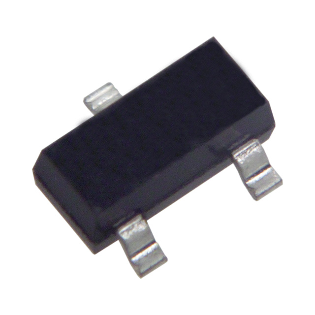
A SOT-23 package, about 2.9 millimeters long. The PIC10F parts use the 6-lead version of this body, the smallest leaded package in the PIC line.
The 6-pin SOT-23 is the workhorse small package. It measures about 2.9 by 1.6 millimeters, with leads on a 0.95 millimeter pitch. Six pins leave two or three I/O lines after power, ground, and the shared programming pins. The PIC10F family lives in this package. The 0.95 millimeter pitch is wide enough that a person solders the part by hand with a fine iron. A standard pick-and-place line also runs it without trouble. The SOT-23 holds the floor for a part a person can still place and rework. A 5-lead version of the same body drops one pin for an even simpler job. Every EDA tool carries the SOT-23 footprint in its library, so a layout starts from a known-good land pattern with no custom work. Decades of parts have shipped in this body, which keeps it cheap, stocked at every distributor, and quick to assemble. A hot-air station or a fine-tip iron reworks it with no special gear.
Eight pins open the next step up. The PIC12F family carries eight pins in an SOIC, an MSOP, or a TSSOP. The SOIC measures about 5 by 4 millimeters, with leads on a 1.27 millimeter pitch a beginner can solder. The MSOP shrinks the body to near 3 by 3 on a 0.65 millimeter pitch. The TSSOP keeps a thin profile for a low-height product. All three place on a standard line. Eight pins give a few more I/O lines for a switch, an LED, and a sensor on one part. The 1.27 millimeter pitch of the SOIC forgives a hand-built board, so a prototype goes together fast. The MSOP and the TSSOP ask for a finer hand or a stencil. All three share the same eight-pin pinout, so a design moves between them when the board tightens.
The 8-pin DFN and UDFN trade leads for pads under the body. A UDFN measures about 2 by 2 or 2 by 3 millimeters, on a half-millimeter pad pitch. The part covers little board and stays low to it. A design gains eight pins in close to the area a 6-pin SOT-23 takes. Many of these parts carry a center pad for the ground connection. Placement needs solder paste, a reflow oven, and an inspection step, since the pads hide under the part. An X-ray or an optical check confirms the joints a probe cannot reach. The center pad carries heat as well as the ground connection, so the layout drops thermal vias under it. A stencil tuned for that pad keeps the part flat through reflow.
The wafer-level package goes smallest. It is the bare die with solder balls on its face, so the package adds almost nothing to the die. Some PIC parts come this way at under two millimeters on a side. The balls sit on a pitch near 0.4 millimeters, which asks for a board with fine traces and small vias. A via-in-pad process places the connection right under a ball on the tightest layouts. This package fits a design where every fraction of a millimeter counts, and where the volume pays for the tighter board process. The die sits exposed on a wafer-level part, so a coating or an underfill shields it from light and mechanical stress. A bare die chips at an edge if a tool slips, so handling asks for more care than a leaded part. The reward is a footprint that adds almost nothing around the silicon.
Small PIC packages, with approximate body sizes. Sizes are typical, not exact. Sources: Microchip package drawings and product data.
Package
Approx size
Pins
Example
Assembly
SOT-23-6
2.9 x 1.6 mm
6
PIC10F200
Hand or line
SOIC-8
4.9 x 3.9 mm
8
PIC12F
Easy, leaded
MSOP-8
3.0 x 3.0 mm
8
PIC12F
Leaded, finer
UDFN-8
2.0 x 2.0 mm
8
small PIC16F
Reflow, pads under
Wafer-level
under 2 mm/side
8 plus balls
select parts
Fine-pitch process
Which PIC parts come that small
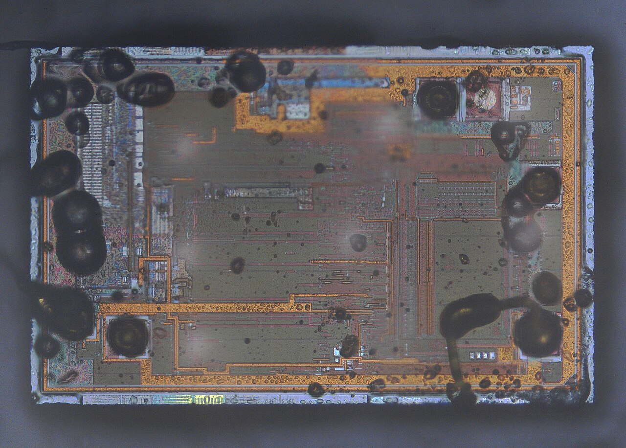
The silicon die of a PIC10F200, with the package removed. The same die ships in every package the part offers; only the body around it changes size.
The PIC10F family is the smallest PIC line. A PIC10F200 holds 256 words of program memory and 16 bytes of RAM. It runs on a baseline core of 33 single-word instructions, with a timer and a few I/O pins. The baseline part carries no interrupt, so the program polls its inputs in a loop. The part suits a single job: a reset supervisor, a fan controller, a simple sequencer, a glue-logic replacement. The PIC10F320 moves to an enhanced core with interrupts, a little more flash, and a PWM for a small motor or a dimmed LED. An internal oscillator runs the part with no crystal, which saves two pins and the board area a crystal and its capacitors take. The few pins each carry more than one function, so the design maps power, programming, and I/O onto them with care. A part this small does one job in almost no room and leaves the board to everything else.
The PIC12F family steps up to eight pins. A PIC12F1xxx part holds a few kilobytes of flash and a few hundred bytes of RAM. It carries a 10-bit ADC, a comparator, and a couple of timers. An MSSP block on many parts speaks I2C and SPI to a sensor or a memory. The extra pins read a sensor, drive an indicator, and run a serial link on one chip. The LF versions run down to 1.8 volts for a coin-cell or a harvested supply. An internal oscillator again removes the crystal and frees two pins for the application. The PIC12F1xxx parts run the enhanced mid-range core, so the same C compiler and the same peripheral libraries carry across the family. A design that needs one more pin or one more kilobyte steps to a bigger part in the same family. The step asks for a recompile and little else.
A small package does not always mean a small core. Some PIC16F parts ship in a 2 millimeter no-lead package with kilobytes of flash, a 10-bit ADC, and the newer core-independent peripherals. Shrinking the package does not shrink the die inside it. The same part number often lists several packages, from a roomy SOIC down to the smallest no-lead body. A design reads the package options and the land patterns Microchip gives for each part on its 8-bit PIC MCU pages. It picks the smallest package the chosen part offers, then checks the pinout fits the board. The same firmware runs whichever package the part ships in, because only the outside changed.
What the small package costs
A small package takes something back for the area it saves. Fewer pins mean fewer I/O lines, so a 6-pin part runs out of connections fast. Less flash and RAM cap the program that fits. A no-lead or wafer package needs reflow, fine traces, and a separate inspection step. Rework on a placed part is hard, since the pads hide under the body. A debug probe has fewer pins to grab, so a design plans its test access early. The tiniest package also costs a little more than a standard one holding the same die. An exotic body can carry a higher minimum order. A bare-die or a no-lead part also limits the rework an assembler does by hand, so a bad joint can mean a scrapped board. A design weighs the saved area against each of these before it commits.
Designing a board around a small PIC
The footprint comes first. A small package needs the exact land pattern the datasheet gives, since a half-millimeter pad error matters at this size. The solder mask and the stencil aperture follow the same drawing. The traces leave the part on a fine pitch a capable fab holds. A design checks its board house can place and route the chosen package before it commits the part. A footprint built wrong on a 2 millimeter part costs a board spin to fix. A solder-mask-defined pad or a non-solder-mask-defined pad changes the copper opening, so the design follows the package recommendation. The stencil aperture sets how much paste lands on each pad, which decides the joint on a no-lead part. Too much paste bridges the pads under the body.
A PIC programs in place over ICSP. ICSP needs five signals: high-voltage program enable on the reset pin, power, ground, the data line, and the clock line. A tiny part has no room for a programming header. A design brings the five signals to test pads or a pogo-pin footprint at the board edge. Low-voltage programming on many parts drops the high-voltage step, so a plain logic level drives the data and the clock. The factory programs the part through those pads on the line. A part can also arrive pre-programmed from the distributor. That drops the programming step from the board. A test point on each of the five signals lets a bed-of-nails fixture verify the board after assembly.
The decoupling capacitor sits as close to the power pin as the layout allows. A small package leaves little room, so the capacitor goes on the back of the board under the part on many designs. A via-in-pad or a pair of vias carries the supply to it. The supply traces stay short, with width enough for the current the part draws. A clean supply matters more on a part with no room for a second capacitor near the pin. A 100 nanofarad capacitor close to the pin handles the fast current the part pulls when an output switches. A larger bulk capacitor on the rail backs it for the slower draw. Both sit as near the part as a crowded board allows.
Assembly sets a limit of its own. A wafer-level part needs a fab that places and reflows chip-scale packages with confidence. A no-lead part needs solder paste, a stencil cut to the right thickness, and a reflow profile the house has proven. The smallest parts ride a panel for placement, since a single tiny board is hard to handle. Automated optical inspection and an X-ray check the joints after reflow. Hand assembly stops near the SOT-23, since the smaller packages ask for equipment. A design built in low volume by hand stays at a leaded package it can place.
The part comes last, after the package and the board are set. A design lists the I/O it needs, the flash the program takes, and the supply the rest of the circuit runs on. It picks the smallest PIC that meets all three and offers a package the board can build. A second source in the same footprint guards the supply, so the design checks which other parts share the land pattern. It confirms the part is in production and stocked before the layout locks. A small board rewards the part chosen with care at the start. A short table of the I/O, the memory, and the supply against two or three candidate parts settles the choice on paper before the layout starts. The part that wins fits the smallest package the board can build and stays in stock for the run.
From prototype to production
A small part is hard to probe on the bench. A first build often starts on a breakout board that brings the SOT-23 or the no-lead part out to a row of header pins. A development board with a larger pin-compatible part proves the firmware before the layout shrinks. The team writes and debugs the code there, with full access to every pin and a debugger clipped on. The firmware proven on the big board is the firmware the small board ships. A breakout step like this saves a board spin that a blind first layout would risk.
Production sets its own steps for a tiny part. The boards run as a panel, an array a placement machine handles as one piece and snaps apart at the end. Tape-and-reel feeds the small parts to the line at speed and in the right orientation. The line places the part, reflows the joints, and then inspects them with optical cameras and an X-ray for the pads hidden under the body. A first-article board gets a full check before the run scales up. The process that can place a 2 millimeter part is the process the whole board is built around, so the part choice and the line are settled together.
Programming fits into the same line. The factory loads the firmware through the test pads as each board passes, or the parts arrive pre-programmed from the distributor and place ready to run. A serial number, a calibration constant, or a MAC address can go in at the same step. The volume that justifies a tiny package usually justifies this automated flow. A board built this way repeats the same on the ten-thousandth unit as on the first.
Sourcing the smallest parts
The smallest package of a part has the shortest stock list. The no-lead and wafer bodies often run thinner in stock than the leaded ones. A design checks the stock and the lead time of the exact package it needs, package code and all. The order goes in early on a tight-package part, since the smallest body refills slowest. A buffer of the small part covers a gap the line cannot afford. The package code rides on the order, since one part number can ship in five bodies.
A second source guards a small-package design. A pin-compatible part in the same footprint from another line keeps the board running if one source runs short. Few parts match a tiny footprint exactly, so the design notes the alternatives early in the layout. A shared footprint helps more on a small board than on a roomy one, since a small board has no space to rework around a missing part. The package, the pinout, and the firmware all line up for a swap to work. A design that picks a widely second-sourced footprint rides out a shortage with less pain.
Common questions about the smallest PIC parts
What is the smallest PIC microcontroller?
The PIC10F parts are the smallest. A PIC10F200 comes in a 6-pin SOT-23 of about 2.9 by 1.6 millimeters. The same family reaches a 2 mm no-lead package. A wafer-level package on select parts drops under two millimeters on a side.
How small can a PIC package get?
Package size sets the floor. PIC packages run from about five square millimeters at the 6-pin SOT-23 down to near the die itself at the wafer level. An 8-pin UDFN sits between, in a 2 by 2 millimeter body. A smaller package leaves a shorter list of parts to pick from.
How few pins does the smallest PIC have?
A 6-pin part gives the fewest. Two pins take power and ground. One or two more carry the in-circuit programming signals, shared with I/O. That leaves about two or three pins for the application. A design that needs more I/O moves to an 8-pin part or larger.
Can I hand-solder the smallest PIC parts?
A SOT-23 solders by hand with a steady iron and a little practice. An 8-pin SOIC or MSOP solders by hand too. A DFN or UDFN hides its pads under the body, so it wants solder paste and reflow. A wafer-level part needs a full fine-pitch process. Low-volume hand assembly stays at the leaded packages.
Do I lose features in a smaller package?
Shrinking the package does not shrink the die. A small package can hold the same core a larger one holds, with the same flash and peripherals. The pins are what a small package gives up, since a 6-pin part has few. A design keeps the features it needs by choosing a part that offers them in a small enough package.
How do I program a PIC with no header room?
A small PIC has no room for a programming header. The five ICSP signals go to test pads or a pogo-pin footprint at the board edge. The factory programs the part through those pads on the production line. A part can also arrive pre-programmed from the distributor, ready to place. A design picks the route that fits its volume and its line.