MCU Boot Time and Production Test Throughput
Boot time is the gap between power reaching a microcontroller and its application doing useful work. Production test throughput is the number of finished boards a line can program, test, and pass in an hour. At volume, both come down to one quantity: time, and what a second of it costs once that second is spent a million times. A slow boot is a cost the user meets once. The same delay returns on the production line, charged against every unit the run will ever make. The seconds that decide both are set in the silicon and the firmware, long before the first reel reaches the line.
Reset to running
Power crossing the threshold does not start the program at once. A power-on reset holds the core down until the supply is stable and the internal regulator that feeds the logic has settled. A brown-out detector sets the voltage at which the part is allowed to run, and it holds reset below that line to stop the core executing on a supply too low to trust. The reset releases. The core fetches its first instruction from the reset vector. On many parts a small boot ROM runs first, reads the option bytes or a boot pin, and decides whether to enter the chip’s built-in serial loader or jump straight to the application in flash. That built-in loader matters twice over. It is how a blank part takes its first firmware over a UART, a USB link, or an I2C bus, and on the production line it is one of the two ways a unit ever gets programmed. Only then does the user’s code begin.
The clock is where the milliseconds hide. A microcontroller wakes on an internal RC oscillator that is ready in a few microseconds, fast enough to start running code straight away. Accuracy is the catch. An internal RC is not precise. Temperature and voltage shift it, so a design that needs a steady clock starts a crystal. A crystal takes time to build its oscillation. The startup is a physical process: an amplitude builds in the resonator until it is strong enough to clock the core. A high equivalent series resistance or a heavy load capacitance stretches that out. A 32 kHz watch crystal, the kind a real-time clock leans on, can take hundreds of milliseconds to start, far longer than the millisecond a megahertz crystal needs. Some parts ship a factory-trimmed internal oscillator accurate enough for a UART or even a USB link. A whole class of designs can then skip the crystal and its startup entirely. Firmware that waits for the crystal before it does anything has handed its boot budget to a passive part on the board.
Two more silicon delays sit in the path. A phase-locked loop multiplies the source clock up to the running frequency, and it needs a lock time of its own, usually tens of microseconds, before the output is steady enough to use. Flash adds its own tax. At a high core clock the memory cannot be read in a single cycle, so the controller inserts wait states. A prefetch buffer or a cache hides them once the part is warmed up and running. Switching the system clock from the RC to the crystal-fed PLL is itself a sequenced step the firmware runs, waiting on each ready flag before it moves to the next. A design can run flat out from the PLL, or hold a lower clock on the RC to start sooner and draw less, a choice the firmware makes in its opening instructions. None of these is large on its own. Together they set how quickly the core reaches full speed.
Reaching the first line of main is not the end of it. The C startup code copies every initialised variable from flash into RAM, clears the zero-initialised region, sets up the stack, and runs the constructors a C++ program registers. A program that keeps more data in RAM pays more for that copy on every start. The copy exists because an initialised variable needs two homes: a value held in flash that survives power-off, and a location in RAM the program can change. The linker records both. Startup code then walks the list, moving each block from its flash home to its RAM one. Trimming what lives in RAM takes the copy off the critical path. Marking large constant tables as const keeps them in flash, out of the copy entirely.
After that the application configures the clock tree, enables the peripheral clocks, and brings each peripheral it uses to a known state. The datasheet quotes a wake time measured to the first instruction. The number a user feels includes all of the firmware work that follows. That gap belongs entirely to the design. A boot that starts peripherals it does not need yet, or blocks on a slow sensor’s warm-up, spends time no datasheet will account for. Bringing up only what the first task needs, and deferring the rest, is how firmware closes that gap. A display can initialise while the first sensor reading is already in flight. A radio stack can come up after the device has shown its first sign of life. The work still happens. It just stops standing between power-on and the first thing the user or the test fixture is waiting to see.
When the milliseconds are the product
For a product that boots once and runs for months, a slow start is a one-time annoyance. The case that bites is the device that wakes thousands of times a day. A battery sensor sleeps to save power, wakes to take a reading, and sleeps again. The wake runs a boot every time. Each one burns current from the moment the oscillator starts until the code finishes and the part can sleep again. A door sensor that reports a state change, a beacon that advertises a few times a second, a tyre monitor that wakes to send a pressure reading: each one’s battery life rests on how cheaply it can wake, do a short job, and return to sleep. A two-millisecond wake, ten thousand times a day, is twenty seconds a day of the chip running flat out for no reason other than starting up. On a coin cell, that startup current sets the battery life as surely as the work the device was built to do. The numbers make the point. A coin cell holds something like two hundred milliamp-hours. A part might draw ten milliamps while it runs. Its sleep current can be a thousandth of that or far less. The device lasts years only because it sleeps almost all the time. Let the wake stretch from one millisecond to five, at the same ten thousand wakes a day, and the active charge quadruples. Every extra microsecond is startup overhead. The startup is the costliest current the device draws. All of it lands in one number a feature list never shows: the battery life the finished product can promise.
Other products meet a deadline at power-up. An engine controller on a vehicle bus has to answer within a fixed window of the ignition turning on. A node still configuring its clocks when the first message arrives has already failed. The split that matters here runs between a cold boot and a warm wake. A cold boot runs the whole sequence: reset, regulator, crystal, runtime, init. A warm wake from a retention mode keeps the RAM alive and the configuration intact. The part skips the bulk of the sequence and resumes in microseconds. Designs that wake often lean on the warm path and treat the cold boot as the rare exception it should be. Sleep comes as a ladder of states. A light stop mode keeps the RAM and the peripheral configuration powered. The wake from it is a resume measured in microseconds. A deep standby cuts power to nearly all of the chip, reaching the lowest current and the slowest wake in the same setting. The deeper the sleep, the lower the current and the longer the climb out of it. A design picks the rung that fits how often it has to wake and how fast it has to answer. The latency a real-time design measures is the whole path from the wake event to the first useful instruction. An interrupt arrives, the wake circuit powers the core, the oscillator restarts, and only then does code run. A hard deadline forces a choice in the sleep mode: keep a fast-enough clock alive through it, or budget for a crystal restart on every wake. Either way, the latency is fixed long before the interrupt arrives.
The boot you pay for twice
Boot time leaves the product and follows the firmware into the factory. Every unit on the test fixture has to power up and reach a known state before a single measurement can run. That wait is the firmware’s own boot time, charged once per unit built. A third of a second of boot, across a million-unit run, is more than eighty hours of fixtures sitting idle before any testing happens at all. A fixture is not free to leave waiting. It is a bench of instruments, a set of pins, and an operator or a handler, all of it paid for by the hour. A unit sitting there doing nothing but booting is that whole bench doing nothing but waiting. Multiply it by the run, and a number that reads as user experience is also the line’s capacity. On the line, that one delay is charged against every unit the run will make, paid in fixtures, operators, and floor space.
Seconds per unit
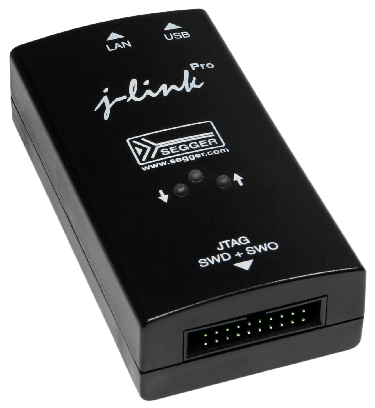
A finished board moves through a fixed run of stations. A clock ticks against every one of them. The board is placed and contacted, its flash is programmed, it boots and runs a self-test, its per-unit calibration is written and verified, and its result is logged before it moves on. Programming is usually the largest block in that run. The firmware image is written into the MCU’s flash over the SWD or JTAG pins. The time it takes is the image size divided by the rate the probe can sustain. Two things cap that rate: the speed of the debug link, an SWD or JTAG clock running at a few to tens of megahertz, and the flash itself, which programs a page at a time and needs a fixed write-and-settle interval for each one. A verify pass then reads the whole image back to confirm it landed, adding its own time. A good probe moves a few hundred kilobytes a second; SEGGER documents its J-Link writing flash at up to several hundred kilobytes a second, with the exact figure set by the part. A megabyte of firmware takes several seconds at a typical rate. That number is charged to every unit the run will make. Parallelism is the way out. A gang programmer drives several targets from one fixture. Ten boards take the time of one. SEGGER’s Flasher ATE, a production tool of this kind, can program up to ten targets at once. Larger rigs chain many such modules together. The arithmetic behind all of this is unforgiving. A line building a hundred thousand units a month meets every second of per-unit programming as roughly twenty-eight hours of machine time over that month. Shaving one second off the cycle frees more than a full day of capacity that was doing nothing but waiting.
Programming loads the firmware. Proving the board works is a separate cost.
The unit boots, runs a self-test that exercises its pins and peripherals, and reports what it found. How the board is tested shapes the time as much as the firmware does. An in-circuit fixture presses spring pins onto the test points and checks the board node by node. A functional test powers the whole assembly and watches it behave. Where pins are scarce, boundary scan walks the signals through the chip’s own JTAG chain. Each trades coverage against speed and fixture cost. A real line usually blends them. Each method also needs its own fixture, designed and built before the first production board arrives. Many products add a calibration step here, where a per-unit value is measured and written to flash or one-time memory: an oscillator trim, an ADC offset, a radio’s frequency correction. Serialisation belongs in the same step, a unique identifier or a MAC address written to each unit and read back to confirm it stuck. Each measurement and each write costs time. Each one the design can skip or speed up returns straight to throughput. Coverage is the lever the test engineer pulls. Every test added finds more faults and spends more seconds. The balance a product strikes between the two is a decision to make on purpose, since leaving it to whatever the fixture happens to check is how seconds pile up unwatched. Skipping a test saves a second on the bet that the fault it would have caught is rare enough to handle in the field. Sometimes the bet is right. A field return on a shipped product costs far more than the test would have, so the seconds trimmed from the line are not always the seconds saved overall.
Boards rarely move one at a time. A panel carries several at once through assembly. A fixture that contacts the whole panel tests them in one pass. First-pass yield then sets the rest. Every unit that fails drops into a slower diagnostic loop. A line timed for the good units can choke on a bad batch. Designing so the common faults are quick to spot keeps the failures from setting the pace. The fastest programming step on the line is the one that is not there. Silicon vendors and distributors will load a firmware image into the parts before they ship. The reels then arrive already programmed. The line only has to test. This moves the programming cost off the production floor onto a supplier who does it in bulk. It fits a firmware image that holds still between builds. The constraint here is logistical. The image has to be final before the parts are ordered. A bug found later means scrapping or reworking programmed stock, so the method rewards a firmware that has stopped changing. Programming need not go through the debug port at all. The same boot ROM that loads a blank part over a serial link is a production path in its own right. A bootloader the firmware carries can take a first factory image and a later field update through the same door. Throughput, in the end, is units per hour: thirty-six hundred seconds divided by the per-unit time, multiplied by the number of units running in parallel. Every second taken out of the cycle, and every fixture added beside it, moves that number. A fixture and the operator beside it cost real money for every hour they run, so a second saved per unit is not a rounding error. At a million units, the seconds are the budget.
What to settle before the first prototype
The seconds on the line and the milliseconds at the user’s hand are both chosen on the day the part and the firmware structure are picked. An MCU with a fast wake from retention, an internal oscillator accurate enough to skip the crystal wait, and a flash the programmer can fill quickly will start fast and test fast. Flash size belongs in the same decision. A part carrying far more flash than the firmware needs costs programming time on every unit and erase time on every rework, a point the guide to sizing flash on a 32-bit MCU takes up on its own. The part that fits the job, with a little headroom, programs and tests faster than the oversized one beside it. The same part also has to be easy to reach. A clean SWD header, test points the fixture can land on, and a programming algorithm the vendor supports at full speed are design-for-test choices that decide how fast the line runs. A larger flash also takes longer to mass-erase, so an oversized part costs again on every reflash during bring-up and rework. Programming speed is its own specification. The vendor’s algorithm and the debug interface set the real rate. Two parts with the same flash size can differ by a wide margin on the line. The datasheet rarely puts that number on the front page. It shows up only when a prototype is timed on the real programmer. Doing that on the first boards costs less than learning it at the first thousand.
Firmware structure is the other half. It resists retrofitting. Firmware boots only as fast as its slowest startup path allows. Bringing up every driver, copying large tables into RAM, and blocking on slow hardware each lengthen that path, no matter how fast the silicon is. Reaching the first useful work quickly, then deferring the rest, is the habit that keeps the boot short on the bench and the test cycle short in the factory. A fast-booting design tends to be a cleanly layered one, since the discipline that defers work is the same discipline that separates it. Firmware can help the factory directly. A dedicated test build, or a test mode the production image drops into, can run a self-check the chip performs on itself, reaching the same parts faster than an external fixture could from outside. Building that path in from the start is cheap insurance for every unit the line will ever test. The same logic runs under both halves of the problem: design the fast path in while it is still a few lines in a fresh codebase, before anything has been built on top of it.
None of this is free to add late. A boot sequence is woven through the startup code, the clock setup, and the driver model. Unpicking it near release is the kind of change that ships bugs. The seconds are cheapest to win at the start, on the day the part is chosen and the first lines of startup code are written. The test strategy earns the same early thought. Deciding how a board will be programmed and tested before it is laid out puts the test points, the debug header, and the panel layout in place by the time the fixture is built. Boards that come back hard to reach are the ones whose test was an afterthought. The same habit wins on both fronts: do the least work needed to be useful, and put off the rest until something asks for it.
| Boot stage | Typical duration | What sets it |
|---|---|---|
| Power-on reset and regulator settling | tens of microseconds to about 1 ms | supply ramp, brown-out threshold |
| Internal RC oscillator ready | a few microseconds | available the moment reset releases |
| Megahertz crystal startup | about 0.5 to a few ms | the crystal, its ESR and load caps |
| 32 kHz watch crystal startup | hundreds of ms | the tuning-fork crystal |
| PLL lock | tens of microseconds | the target frequency |
| C runtime, copy and clear | microseconds to ms | the size of the RAM data set |
What is a typical MCU boot time?
It varies by orders of magnitude. The silicon’s reset-to-first-instruction can be microseconds. The time to a running application is set by the crystal startup and the firmware’s own init. A 32 kHz watch crystal alone can take hundreds of milliseconds, far longer than a megahertz part’s millisecond. The number that matters is the one measured to the first useful work. Firmware sets the bulk of it.
How do I make an MCU boot faster?
Start on the internal RC oscillator and switch to a crystal or PLL only when accuracy needs it; copy less into RAM at startup, and keep constant tables in flash; bring up only the peripherals the first task needs; prefer a warm-wake retention mode where the design allows. Each one takes time off the path before the application runs.
Why does boot time matter on the production line?
The test fixture has to wait for each unit to boot and reach a known state before it can test it, so the firmware’s boot time is paid once per unit. Across a large run that adds up to hours of fixture time spent waiting. The number a user feels once is the number the factory feels on every board.
What is the biggest contributor to production test time?
Usually flash programming. The time is the image size divided by the programming rate. A megabyte image takes seconds. That cost lands on every unit, so gang programming several at once, raising the programmer’s clock, and pre-programming the parts are the main levers for cutting it.
Can I have the parts programmed before they reach my line?
Yes. Silicon vendors and distributors offer factory programming. Reels then arrive with the firmware already in flash. The line only has to test. It suits a stable image that holds still between builds, and it takes the whole programming step off the production floor.