Inductors and Ferrite Beads for Power and EMI
An inductor and a ferrite bead are both passives wound from copper on a magnetic core. They look alike on a board and sit close on a schematic. Each one answers to its own set of numbers. A power inductor is chosen on its saturation current, its DC resistance, and its inductance value. It has to carry a converter’s current, stay clear of saturation, and lose little of that current as heat. A ferrite bead is chosen on its impedance at a stated frequency and its rated current. Its job is to block noise and leave the supply line it sits on intact. Treating one as the other is the error behind a long list of failed power lines and failed EMI fixes. The choice starts with one question: does the job in front of you need a power part or a noise part? A board carries both. Power inductors sit on its converter outputs. Beads scatter across its supply and signal lines. Reading each part on its own numbers is what holds a supply steady and a spectrum clean.
Power inductors and saturation
A power inductor sits in a switching converter. Its current ramps up and down every cycle. The first number that matters is the saturation current, the point where the core stops storing more field and the inductance collapses. Below that point the part behaves as its rated value. Past it the inductance falls away and the current spikes, which a converter reads as a fault or runs on until something fails. The inductance value itself sets how hard the current ripples each cycle. The volt-seconds the converter applies drive a current ramp that runs inversely with the inductance, so the bigger the value, the smaller the ripple. The value gets chosen with the switching frequency to set the ripple where the design wants it. Stray too low and the ripple stresses the part and the capacitors around it. Stray too high and the part costs board size and DC resistance. The value is a balance struck before the current ratings even enter the choice. The switching frequency moves that balance, since a faster converter holds the same ripple on a smaller inductance.
The trouble from getting this wrong is specific. Knowing why undersizing the saturation current causes trouble starts with the peak current the inductor sees. That peak is the average load current plus half the ripple. It has to sit below the part’s saturation rating with margin. A part chosen on the average current alone saturates on the ripple peaks. Its inductance drops, the ripple grows, the converter heats, the loop turns unstable. So the saturation current gets read against the peak the part sees. The average current goes to a separate heating check. The datasheet plots inductance against current and shows where it rolls off. The rolloff runs from the gentle slope of a soft core to the abrupt give of a hard one. The part gets chosen with its entire curve in view. The single number on the label settles nothing on its own.
The other steady cost is resistance. Working out how a small DCR still costs efficiency comes down to the current squared times the DC resistance of the winding. That loss runs the whole time the converter delivers current, so even a few tens of milliohms turn into a real fraction of a watt on a high-current rail. A lower DCR takes a thicker winding and a larger part, so the choice trades size for efficiency. A design reads the DCR against the current it carries and the heat it can shed. The DCR also sets the temperature rise. The winding’s own loss is what heats it. A part rated for a current on saturation can still run hot on resistance, so the two ratings get read together. The core adds its own loss on top, giving up energy each cycle to hysteresis and eddy currents. A faster converter and a bigger ripple raise that core loss. The copper loss and the core loss together heat the part and feed the efficiency bill. A datasheet that lists only the DCR tells half the story on a high-frequency rail.
Every power inductor carries two current ratings. The saturation current marks the magnetic limit, the point where the core holds no more field and the inductance starts to collapse. The heating current marks the thermal limit, the point where the winding’s own loss lifts the part to its temperature ceiling. A part carries both at once. A design checks its peak current against the saturation rating and its average current against the heating rating, since the two can sit far apart on one part. When the ripple is high on a light average load, the peaks reach the core limit long before the average heats the winding, so the saturation number holds the part. When the current is heavy and steady, the winding overheats before the core saturates, so the heating number holds it. The binding limit moves with the application, so the part gets read on whichever one it reaches first and sized with margin against that one. The core material shapes the saturation on top of this. A ferrite core gets generous margin, since its inductance falls off a cliff once the field fills. A powdered-iron or composite core, forgiving in its slow rolloff, runs closer to its rating. That forgiveness draws a converter that sees occasional current spikes. The datasheet shows all of this as a curve of inductance against current. A design reads where the curve has fallen to perhaps eighty or seventy percent of nominal and treats that as the usable limit. The labeled saturation figure sits above that working point. The inductance at the peak current is what sets the ripple and the stability. A part run past its real rolloff feeds a ripple larger than the budget and a loop less stable than the model. Margin on saturation is the cheapest protection on the rail, since a part one size up in current costs a little board area against the recall a field saturation brings. So the margin gets set generously and checked at the highest load and the lowest inductance the part is specified to hold.
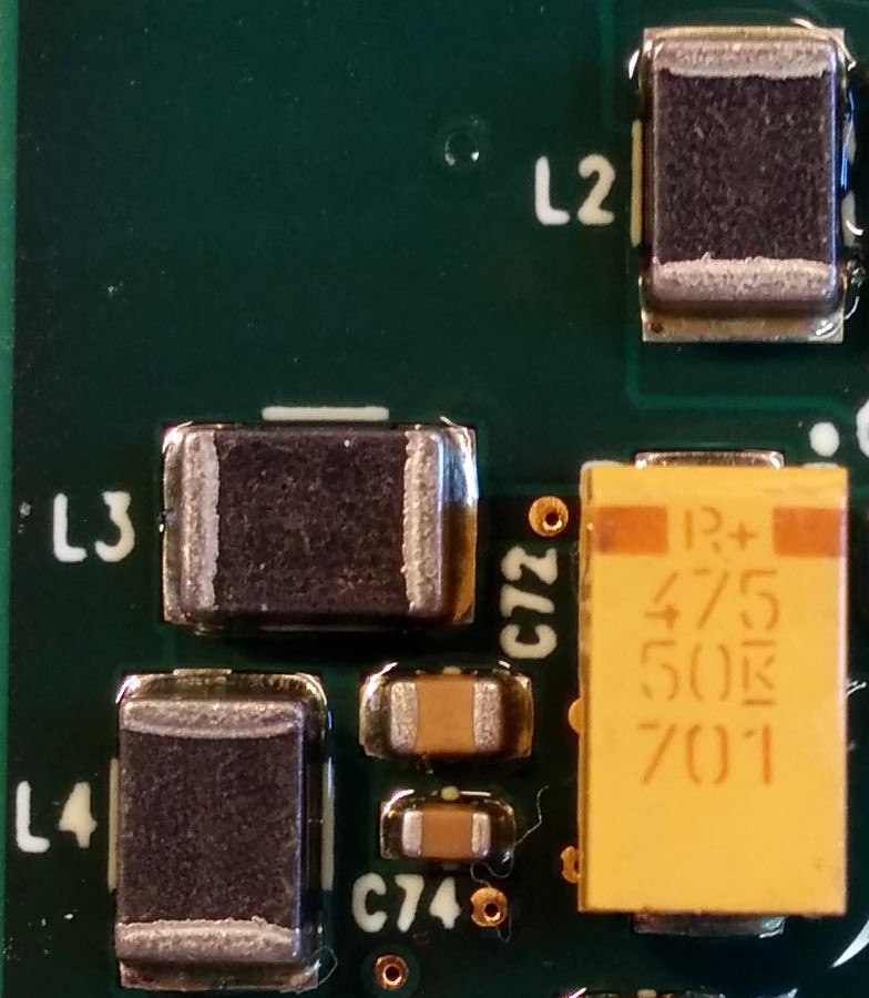
Shielding is the third axis. Weighing the EMI gain and the cost of shielded inductors turns on one trade. A shielded part keeps its magnetic field to itself. It radiates less into nearby traces and sensitive circuits. A shielded part costs more. It sometimes carries a higher DCR as well. A dense board near an antenna or an analog front end reaches for the shielded part. The shielding gets matched to the EMI the design has to meet.
Self-resonance and the bead handoff
An inductor stops behaving as an inductor above its self-resonant frequency. The winding’s own capacitance takes over there and the impedance falls away, so a part used near that frequency behaves as a capacitor and stops filtering. A power inductor on a switching rail runs well below its resonance and ignores it. A part used to filter at high frequency gets read on its resonance the way a bead gets read on its curve. This marks where the inductor ends and the bead begins. Above a few tens of megahertz a wound inductor has lost its impedance to its own capacitance. A ferrite bead takes over the job of stopping the noise in that band.
Power inductors come in a few constructions. The type suits different rails. A wirewound part on a drum or a toroid core gives a low DCR and a high current for its size, the default on a power rail; a shielded version adds a sleeve or a magnetic coating that holds the field in. A molded part buries the winding in a composite core, which gives a soft saturation and a rugged, low-radiation body for a dense board near sensitive circuits. A multilayer or thin-film part packs a small value into a tiny case for a light load or a high-frequency point-of-load, trading current for size. The construction sets the saturation behavior, the DCR, the height, and the radiation. A flat composite part and a tall wirewound part at the same inductance bring their own DCR and radiated field to the board, so the type gets read alongside the value and the current. The core material runs underneath all of it: ferrite for the high-frequency low-loss rails, powdered iron or a composite for the high-current soft-saturating ones. Type and material get read together with the electrical numbers.
The inductor vendors
The premium end of the power-inductor market runs on a few makers known for tight specs and reliable data. Reaching for Coilcraft LPS and XAL in premium power designs buys a part whose saturation and DCR are characterized with care, whose models match the bench. A tight, high-performance converter pays for that. The availability of the low-profile high-current Vishay IHLP covers the parts a dense, high-current board reaches for, a composite-core family that takes a hard current in a flat package, broad enough in stock to design around. The two anchor the high end on their own footings: one on characterized data and tight tolerance, the other on raw current density in a flat case. Both publish the saturation and heating curves a careful design leans on. That data is what the premium price secures.
The breadth of a line decides as many designs as its peak specs. Knowing when to choose Würth WE-LHMI and WE-HCI covers a wide catalog with free samples and solid data, a help to a design that wants one supplier across many rails. The Sumida CDRH applications cover a long-established shielded drum family that fits the ordinary buck-converter rail at a sensible price. The mid-market makers compete on breadth and availability. A design that needs a workable part across a dozen rails, with no qualification of each one, reaches for a wide catalog with good stock and clear data. The free samples and online design tools these makers offer speed the early work. A part in hand and a model that matches the bench let a converter rail settle quickly, so the design pays the premium only on the rails that need the fully characterized part.
One job needs the field kept in. The Bourns SRR shielded inductors and EMI cover the semi-shielded and shielded drum parts a design drops onto a rail that has to pass radiated-emissions limits. The current uses of J.W. Miller axial inductors cover the leaded parts that still fit a through-hole filter, a high-current choke, or a repair where a surface-mount part will not do.
Weighing Chinese inductors against Coilcraft measures how far a cost-driven part has closed the gap on saturation, DCR, and data quality. For many ordinary rails that gap has closed far enough, so a design reads the curves and the lot consistency before it commits the cheaper part to a rail that matters. The gap is narrowest on the ordinary buck and boost rails, where a cost-driven part holds its saturation and DCR well enough and the lot-to-lot spread is tight enough to design around. A design reserves the premium part for the rails where the margin runs thin. That discipline captures the saving and keeps it off the hard rails.
Ferrite beads
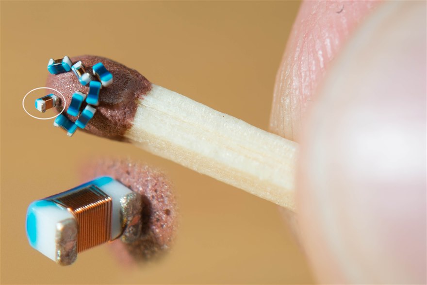
A ferrite bead is a frequency-dependent resistor: low impedance at DC, a peak of resistance at high frequency where it turns noise into heat. It passes the supply current and absorbs the noise riding on top. The bead is rated by its impedance at a stated frequency, usually a hundred megahertz, and by the DC current it carries before it saturates and loses that impedance. At low frequency the bead is a small inductance and passes the signal. In its working band the ferrite turns lossy and the bead becomes a resistor that takes up the noise and sheds it as a little heat. A bead is sorted by the band it targets. A part tuned to suppress noise around a hundred megahertz does little at a gigahertz. The reverse holds too. The bead gets matched to the frequency of the noise the design has to kill. Makers and grades use different materials. A high-current bead trades some impedance for the ability to carry more bias, so the choice reads the impedance, the current, and the target band together.
The market leaders set the reference. The noise suppression of Murata BLM ferrite beads covers the broad family a design reaches for by default, sorted by impedance, current, and the band each part targets. The interchangeability of the TDK MPZ and Murata BLM covers how closely the two cross-reference, a second source a design leans on once it checks the impedance curve and the current rating, past the value alone. The two makers between them set the catalog the rest of the market cross-references against. A bead specified as a BLM or an MPZ part is one a buyer can source widely. The cross-reference holds as long as the impedance band and the bias rating match, past the nominal impedance. A design that pins a bead to one maker, with no check of the proposed equivalent’s curve, can find the substitute peaks in a different band and lets the noise it was meant to stop pass straight through.
The trap is reading the part on one number. Understanding the limits of selecting a bead on its impedance curve starts with one fact: the rated impedance is measured at a stated current. A rising DC bias pulls it down. A bead carrying real current delivers far less than its headline figure. The impedance is a mix of resistance and reactance. Only the resistive part damps noise. A bead used below its resistive band fails to shed the energy. It stores that charge and can ring with a nearby capacitor, raising a peak where the design wanted a notch. A bead chosen on its hundred-megahertz number alone, with no read of the bias derating and the resistive band, often makes the noise worse. The part gets read on its full curve at its real operating current.
Using a bead on a rail
Knowing why a bead sits next to a digital power rail is about keeping the switching noise a digital chip makes from traveling back down the supply into the analog or RF section that shares it. The bead isolates the noisy local rail from the clean one. The bead is paired with decoupling capacitors on each side. The design watches the LC resonance the bead and those capacitors form. It damps that resonance where the peak would fall in band.
A bead is the wrong part on a rail that draws heavy current. It loses its impedance under bias and adds resistance the rail never wanted. That single mistake sits behind a great many EMI fixes that cost a rail its regulation.
The bead forms a filter with the capacitors on either side. That filter has a resonance a design has to place with care. A bead and a clean ceramic capacitor make a high-Q LC circuit. Land its resonance on a frequency the noise carries and the filter peaks there, amplifying the same noise it was placed to stop. So a design either picks a lossy bead whose resistance damps the resonance or adds a small damping resistor to flatten it. This is why a bead dropped onto a rail on instinct sometimes raises an emissions peak that was not there before. The bead, the capacitors, and the damping get designed together as one filter, with no part dropped onto the rail on its own. The DC resistance of the bead is small. At the load current it drops a voltage and burns a little power. A bead on a rail pulling an amp drops tens of millivolts and warms itself. A sensitive low-voltage rail cannot spare that drop. The right reach on a heavy rail is a proper inductor or a filter matched to the current. The bead is kept for the signal lines and the light local supplies, where its loss of impedance under bias does not bite.
Common-mode and differential chokes
Some noise needs a choke in place of a bead. The kind of choke turns on the kind of noise. Choosing between common-mode and differential-mode chokes starts with where the noise flows. A common-mode choke wraps both lines on one core. It ignores the signal current that flows out one line and back the other. It presents a high impedance only to the common-mode noise that flows the same way on both lines, the noise a cable radiates. A differential-mode choke is a plain inductor in one line that blocks the noise riding along the signal itself.
A choke gets read on the same numbers as any inductor, with its job added. A common-mode choke is chosen for its common-mode impedance across the noisy band and its current rating. It goes where the cable meets the board to catch the noise before it leaves. A data line uses a choke wound to pass its differential signal cleanly and block the common-mode noise, so the part is matched to the signal it has to leave alone as carefully as the noise it has to stop. A common-mode choke on a USB or an Ethernet line is specified to pass the data rate without distortion. That sets how tightly the two windings couple and how much leakage inductance the part can have, since the leakage acts on the signal as a differential inductance and rounds the edges. The current rating matters too. A choke on a power input carries the full supply current through both windings and saturates if it is undersized, so a power-line common-mode choke gets read on its current the way a power inductor does. A design that knows which mode dominates picks the choke that fits, skipping the habit of stacking both and hoping. A board that fails its radiated-emissions scan often traces the trouble to a missing or undersized common-mode choke at the cable entry. The cable is the antenna that carries common-mode current out as radiation, so the choke goes in where the cable meets the board. Its size follows the band the scan flags and the current the line carries.
How they get chosen and sourced
An inductor is read on its saturation current and its DCR, with the inductance value a step behind those two. A bead is read on a different pair, its impedance curve and its rated current. A substitution that matches the value can still fail if its saturation, its DCR, or its bias derating fall short of what the rail was built around. A broad-line distributor that carries the power inductors and the ferrite beads across the values, the current ratings, and the case sizes gives a design room to match each part to its rail. The premium part goes on the rails that need it. A checked equivalent on the full curve covers a part that runs short. The saturation current and the DCR are the constants a power rail answers to. The impedance curve and the bias rating are the constants a bead answers to. So a part gets checked on the curve and the rating, past the headline value, and a second source the same way. Each kind of part has its own supply picture. The beads and the commodity inductors come from several makers. They cross-reference cleanly. The premium power inductors and the custom magnetics carry longer lead times and fewer drop-in equivalents, so a design that commits to a characterized part builds that lead time into its schedule. A part qualified to the automotive grade carries the screening a car program needs, which narrows the field of makers. A design reads the grade and the lead time against the market it ships into, the way it reads the electrical numbers.
Read the curve, past the headline
Name the job first. A power inductor stores energy. A bead blocks noise. The two never swap. Size the inductor’s saturation current against the peak current with margin. Read its DCR against the efficiency and the heat. Shield it where the EMI calls for it. Read a bead on its impedance at its real bias current and its resistive band, past the headline number, and keep it off a heavy-current rail. Match a choke to the mode of the noise it has to stop. Design the bead, its capacitors, and any damping as one filter.
The one habit that heads off the worst trouble is reading the curve. The saturation current, the impedance, and the bias derating all live on curves that the one number on the front of the datasheet hides. The fifteen pages below take the inductors, the beads, and the chokes one at a time. Each one turns on the number that decides whether a part holds up a rail or clears a spectrum. Each one gets read on the curve the datasheet plots beneath that headline figure.
Common questions
Can a ferrite bead go on a power rail that draws an amp or more?
A ferrite bead loses its impedance under DC bias and adds series resistance. On a rail pulling an amp it drops tens of millivolts and warms itself. A sensitive low-voltage rail cannot spare that drop. A heavy rail wants a proper power inductor or a dedicated LC filter. The bead stays on a signal line or a light local supply.
Why did adding a ferrite bead create a new noise peak?
A bead and a clean ceramic capacitor make a high-Q LC circuit. The pair has a resonance. A resonance that lands on a noise frequency amplifies that noise. The fix is a lossy bead whose resistance damps the peak, or a small series resistor at the capacitor. The bead, the capacitor, and the damping belong together as one filter.
Which current rating do I size a power inductor to?
A power inductor carries two ratings. The saturation current is the magnetic limit, set against the peak current the part sees. The heating current is the thermal limit, set against the average current. When the ripple is high and the load light, the saturation number holds the part. When the current runs heavy and steady, the heating number holds it. The part gets sized to whichever limit it reaches first.
Does a low DCR always mean a more efficient inductor?
DCR drives the conduction loss, the current squared times the resistance. That loss matters on a high-current rail. The core adds a separate loss to hysteresis and eddy currents. That core loss rises at high switching frequency. A datasheet that lists only the DCR tells half the story on a fast rail. Efficiency reads the copper loss and the core loss together.
When do I need a common-mode choke instead of a ferrite bead?
A cable that fails a radiated-emissions scan is usually carrying common-mode current, the same direction on both wires. A ferrite bead on a single line does nothing for that current. A common-mode choke wraps both lines on one core and blocks the common-mode current alone. The choke goes at the cable entry. Its rating follows the band the scan flags.