Compressed air at cement plants gets blamed for almost nothing considering how much it breaks. A kiln upset gets investigated as combustion. Conveying slowdowns end up in the maintenance system as mechanical faults. Bag filter opacity exceedances get chalked up to bag condition or fan performance. The people investigating have backgrounds in chemistry and thermal engineering. The compressor room is maintained by a different crew who file different work orders and attend different meetings.
Cement is a hard environment for this equipment. Dust loading on intake filters exceeds the rated ambient by a factor of fifty in the worst locations on site. Demand swings a third when a mill trips. Cooling systems struggle on summer afternoons across the whole band from Casablanca to Chennai. Some of these topics are well covered in the general compressed air literature. Others are specific to cement and concrete and get almost no coverage anywhere.
Shared Versus Separate Air Systems
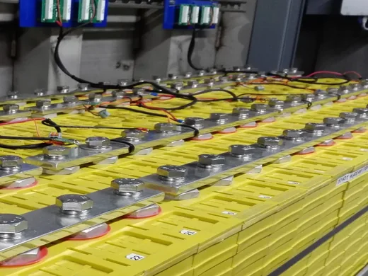
Process air handles conveying, aeration, pulse cleaning, and utility blowdowns at 3,000 to 12,000 cubic meters per hour depending on the plant, Class 4. Instrument air feeds positioners, actuators, I/P converters, and purges at 500 to 2,000 cubic meters per hour, Class 1.2.1.
Whether these two networks share compressors or run independently is a decision that gets made once during engineering by someone filling out a design basis document, and then sits in the infrastructure for the life of the plant, which in cement is often thirty years or more. It is possible to retrofit separate systems later. It is expensive and disruptive and it almost never happens.
On a shared system the instrument air branch draws from the same header as the process air, with additional drying and filtration on the branch. On a diagram this looks clean enough. On a running cement plant at 2 PM on a Tuesday when the raw mill bag filter has just restarted after a maintenance stop and a conveying cycle has begun on the long line to silo 4 and the blending system has opened aeration valves on silos 1 through 3, the header is down half a bar or a full bar and the instrument air dryer is trying to dry air at an inlet pressure it was not designed for.
The dryer performance depends on inlet pressure. Lower inlet pressure means the air moves faster through the desiccant bed. Contact time drops. Moisture removal gets worse. For thirty or sixty or ninety seconds, instrument air quality drops below the Class 1.2.1 spec. Wetter. Dirtier.
A positioner does not care about one thirty-second exposure to wet air. A positioner does care about eight hundred thirty-second exposures over the course of a year. The count depends on how many process consumers the plant has and how often they happen to overlap, which on a large plant with three mills and four bag filters and a dozen silo circuits is several times per shift.
Spool valves pick up contamination gradually. The friction changes. The response gets slower. The DCS auto-tuning adjusts parameters to compensate. The operator sees the kiln running slightly less tightly than it used to and cannot point to a specific date when it changed. The instrument technician replaces the positioner during a shutdown and writes normal wear on the work order. The replacement starts drifting within six months because it breathes the same air the old one did.
This is the kind of problem that can persist for the entire operating life of a plant because there is no acute failure event to trigger an investigation. The positioner did not explode. The kiln did not trip. Control quality degraded by a few percent. Everyone adjusted. The replacement rate became the baseline.
Design Principle
Separate compressors, dryers, receivers, headers. Cross-tie for emergency backup with its own treatment. More money during construction. Less money during the following thirty years. Those two numbers hit different budgets. The people approving the construction budget in year zero are not the people absorbing the maintenance cost in year twelve. This dynamic between capital and operating expenditure shows up repeatedly across compressed air decisions in cement plants.
Old carbon steel instrument air piping is another trap. Plants that have run fifteen or twenty years with carbon steel between the dryer and the instruments develop internal corrosion. Fine iron oxide, downstream of the last filter so the filter cannot catch it, rides the airflow to the positioner. The entire treatment chain can be performing perfectly at the dryer outlet and the positioner still gets contaminated air because the pipe itself is the source. Stainless or copper for the last 15 to 20 meters to each critical instrument. Per-run cost less than the positioner at the end of it.
Compressor Types
Oil-free screw for instrument air. Oil-injected for process. Centrifugals for base load on big plants. Choosing between these categories is generally obvious from the application. The engineering problems specific to cement are more interesting than the selection question itself.
Oil-free screw machines run two-stage intercooled, Class 0. Premium of 40 to 60 percent over oil-injected, sometimes more. The intercooling between stages reduces the moisture load on the dryer. In tropical plants, dryer maintenance cost drops over a few years. That saving accrues to the dryer maintenance budget and is invisible during compressor bid evaluation. Catalog FAD is quoted at 35°C. At 45°C ambient, output drops and cooling effectiveness drops and humidity is high, all at the same time on the same afternoon.
Shaft seals sit between the gearbox and the compression chamber. When the seal wears, gearbox oil crosses into the air path. Machine still labeled Class 0. The symptom shows up at the dryer or the carbon filter as premature media degradation, not at the compressor where the problem originates. The seal service interval is shorter than the airend overhaul interval. Most plants replace seals during overhauls rather than on their own schedule.
Class 0 at the compressor discharge does not mean Class 0 at the point of use. Intake air at a cement plant carries hydrocarbon vapors from diesel equipment and fuel handling. These pass through. Activated carbon filtration downstream handles them. Most Class 0 installations at cement plants do not have this filtration.
Oil-injected screw machines for process air see downstream treatment elements foul faster than published intervals. Cut change intervals based on site conditions. Synthetic lubricant extends airend overhaul intervals over mineral oil. Lock consumable pricing over 40,000 hours in the purchase contract or watch the cheap compressor with the expensive proprietary filters win the bid. Reciprocating machines still exist for pressures above 10 bar and for dense-phase conveying with mostly-idle duty cycles where near-zero idle power consumption matters.
Centrifugal Surge and Fouling
Centrifugal compressors on cement plant base-load duty run single frame at 5,000 to 30,000 cubic meters per hour and 6 to 8 bar gauge. Inherently oil-free. Few wearing parts.
Surge occurs when impeller flow drops below a critical threshold and the aerodynamic flow separates and reverses. The pressure oscillation can destroy the machine in seconds. In refining or gas processing, demand is usually stable enough to size the machine above the surge line at minimum load. Cement does not allow this because the demand swing between all-mills-running and kiln-only can be a third or more of total air consumption, and the transition happens in minutes when a mill trips.
Blow-off valves vent air to atmosphere to keep impeller flow above the limit. During kiln-only periods the energy going through the blow-off is substantial and gets absorbed into the monthly electricity bill without separate tracking. Predictive anti-surge controllers calculate the boundary from live conditions and coordinate guide vanes and recycle valve. On a large frame the energy savings justify the controller within a couple of years.
Fouling is where this gets specific to cement. Trace calcium dust passes through intake filtration. The particles are fine enough to pass the filter and heavy enough to deposit on impeller blades and diffuser vanes under the centrifugal loading in the stage. The buildup is slow. There is no alarm for it. There is no instrument watching it. Daily data does not show it because the performance shift is smaller than measurement scatter and instrument drift.
Over many months, the deposit changes impeller aerodynamics enough to shift the compressor map. Surge line migrates to higher flow. Efficiency drops. A machine that ran at 70 percent flow with generous surge margin at commissioning starts seeing surge at 78 or 80 percent. The anti-surge controller is running a map from commissioning. The controller calculates margin based on where the surge line used to be. The map has moved. The controller has not.
Here is what the diagnostic sequence looks like from the maintenance side. The machine surges. Maintenance investigates. They check the anti-surge controller. Logic is correct. They check the recycle valve. Strokes fine. They check the inlet guide vanes. They check the inlet filter differential pressure. Normal. They check the vibration trending. No bearing issue. They check the oil system and the cooling water temperature. Normal. Everything in the protection system tests good. The surge happened anyway. The report says spurious surge event, cause undetermined. File closed.
Two months later it happens again at a slightly higher flow because the fouling has progressed. Same investigation. Same result. Each time, the investigation finds nothing wrong because the investigation checks the protection system and the protection system is functioning correctly against a map that is no longer accurate.
Performance testing reveals the map shift. Three or four operating points across the flow range, controlled conditions, measuring inlet and discharge temperature and pressure, flow, and motor power, plotted against the commissioning curves. The shift in the surge line shows up immediately. Online water wash restores the map on machines designed for it. Offline cleaning during a kiln stop works on any machine. After cleaning, the performance map returns to near-original condition and the anti-surge controller’s commissioning map is valid again.
Best Configuration
Large plant configuration is centrifugal base load with VSD oil-free screw machines for trim. The screw machines absorb demand swings and keep the centrifugal away from surge during mill-off periods. They also cover when the centrifugal goes down for cleaning.
Bag Filter Pulse Cleaning
Pulse cleaning on a kiln or raw mill bag filter accounts for 15 to 25 percent of total plant compressed air, and the waste is large and fixable without capital expenditure.
New bags commission with high permeability and low differential pressure. Pulse controller at factory defaults, interval around 15 to 20 seconds between pulses, duration 100 to 150 milliseconds, cleaning mode set to time-interval. Air consumption modest.
Years pass. Bags age. Permeability drops. The residual dust cake gets thicker and more tightly bonded. Baseline differential pressure rises. The alarm triggers more often. The control room operator has this alarm competing with dozens of others. The alarm setpoint gets bumped upward to suppress it. From 12 mbar to 15. Later to 18.
The pulse controller has a differential-pressure-response algorithm. It sees the higher dP. It shortens the interval between pulses. From 18 seconds to 14. Then 12. Then 10. The controller does it automatically. Each reduction consumes more compressed air. Over thousands of hours the consumption climbs to double or triple the commissioning value without generating any step-change alarm.
Five or seven years later, bags are old, baseline dP is permanently high, the alarm setpoint has been bumped multiple times, the pulse interval is down to 6 or 8 seconds, and the pulse duration is still at the factory default because that parameter lives three menu levels deep and the only person who touched it was the commissioning engineer who left site years ago.
The re-optimization takes a competent process engineer two to three days at the controller, physically present because the dP response to each parameter change needs to be observed over a few hours. Walk the pulse interval up in increments. Watch dP. Keep going until dP starts climbing beyond what is acceptable for that bag condition. Back off one increment. Cut the pulse duration: the factory default of 120 to 150 milliseconds is conservative, and for most cement kiln dust on polyester needlefelt bags, 60 to 80 milliseconds delivers an effective cleaning pulse. Switch from time-interval cleaning to dP-triggered cleaning so the system matches its air consumption to the cleaning demand. Combined reduction runs 20 to 40 percent relative to the drifted settings.
Key Barrier
The bag filter sits under the process department. The compressed air system sits under mechanical maintenance. Neither department’s performance metrics capture the other’s energy use. The process engineer does not track bag filter air consumption. The maintenance engineer does not have login credentials for the bag filter controller. The optimization requires someone who can work across both domains and who has authority to change parameters on equipment belonging to another department.
Batch Plants
Concrete batch plant demand comes in short bursts. Bin gate actuation, vibrator operation, mixer drum blowout. Ten to fifteen seconds of draw, then minutes of near-zero consumption. The receiver tank does the work in this application. If the receiver is undersized, every burst drops tank pressure far enough that the compressor slams from unloaded to loaded and back. Loading valve hammering. Motor inrush. Contactor arcing. Motor thermal protection tripping at 3 PM with four trucks waiting.
Size the receiver for at least 3 minutes of compressor run time at worst-case peak demand. VSD screw machines track the intermittent curve. Two-stage intake filtration because concrete plants generate cement dust and aggregate dust and sand and admixture aerosol all at the same time and the standard single-stage panel element cannot handle the combined loading.
Mixer washout air gets left out of the demand profile during sizing. At end of production, high-pressure air blasts residual concrete out of the drum and chute, a large sudden draw arriving when the batching cycle is winding down and the compressor has likely unloaded. If washout was not in the profile, the last operations of every shift run slow.
Precast and Cold Climate Issues
Vibrating tables need sustained flow at constant pressure for 30 to 90 seconds. Pressure variation during consolidation produces surface defects. Dedicated compressor and local receiver near the table.
Cold-weather drum blowout at ready-mix plants is a hidden one. Compressed air carries moisture into the drum after washout. Truck parks overnight in freezing temperatures. Moisture freezes on the walls and mixing fins. First load mixes poorly. Blades crack. Rejects accumulate through winter. Gets called seasonal variation or driver error or cold-weather mix sensitivity because the symptom is in the concrete quality data and the cause is in the air system and the two data streams never cross the same desk. A point-of-use desiccant dryer on the blowout line stops the ice. Annual winter cost of rejects and blade damage at a single plant exceeds the dryer cost by a wide margin.
Piping, Filtration, Room
Header velocity under 6 to 8 m/s per CAGI recommendations. Pressure drop across the distribution on most cement plants is 0.5 to 1.5 bar over 500 to 1,500 meters. Plants that expanded compressor capacity without resizing pipe are above design velocity and friction loss goes with the square of velocity. Ring mains halve velocity and pay back in compressor energy within about 18 months.
Calcium hydroxide paste buildup inside process air headers comes from moisture reacting with entrained cement dust on pipe walls. The bore narrows over a decade or more. Attributed to demand growth because the restriction develops gradually. Drains at low points and periodic pigging. Aluminum piping with push-fit connections has no corrosion, higher material cost, lower lifecycle cost.
Ambient dust around a cement plant runs 5 to 50 mg/m³ against intake filters designed for 0.5 to 1 mg/m³. Multi-stage pre-filtration or self-cleaning pulse-jet intake assemblies on elevated ducts from the cleanest location available. A breached intake filter means dust in the airend. Heatless desiccant dryers lose 15 to 18 percent of output as purge; heated and blower-purge types lose far less. Activated carbon beds saturate within months in cement environments with ambient hydrocarbons, and the dP gauge gives no indication because saturated carbon has similar flow resistance to fresh. Room placement is set by civil engineering and ends up near mills or clinker handling, so an elevated intake duct compensates. Epoxy floor and stainless drains during construction because condensate plus cement dust forms calcium hydroxide sludge.
Energy, Sizing, Remaining Topics
Each bar of header pressure reduction saves about 6 to 7 percent of compressor energy. Parasitic loads from unauthorized connections accumulate over decades and can reach 10 to 20 percent of demand on old plants. Pulse valve manifold diaphragms are a leak source that ultrasonic surveys miss because the leak is internal; thermal imaging with the controller off reveals them.
Nameplate summation overestimates demand. Diversity factor in cement is 0.60 to 0.75. Concrete batch plants below 0.40. Profile demand over a full cycle. Growth margin 10 to 15 percent. Standby redundancy rather than oversizing: three machines at 50 percent, two running, one spare.
At altitude, air density drops, FAD drops, cooling drops, motor starting gets harder on the bus, and desiccant dryer purge calibrated at sea level underperforms because the air is thinner. Alternative-fuel systems add demand not in the original air balance; at high substitution rates with chunky solid fuels, pressure pulses from plug-and-slug flow in injection lines disturb kiln control positioners, and a dedicated compressor eliminates it.
Intake filters checked daily, replaced on dP threshold. Oil analysis every 1,000 hours. Coalescing elements at 4,000 hours regardless of gauge because cement dust creates bypass channels while the gauge reads normal. Monthly fin cleaning in humid climates. Vibration monitoring on airend bearings. Track system specific energy weekly. Heat recovery from compressor waste heat is technically available and mostly wasted due to piping distance. Master controllers save over cascade sequencing. Decarbonization technologies now in pilot stages will change what compressed air systems need to serve, so build in space during construction.