







Probe engineering
Interchangeable Probe Connector Engineering Design Handheld Ultrasound
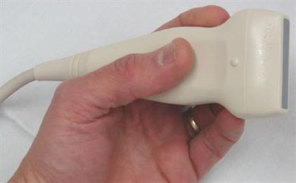
An interchangeable handheld ultrasound puts the processing in a base and the transducer in a head that detaches. The join between the two is a small piece of engineering that carries a heavy load. It has to pass dozens of electrical signals without smearing them, hold the head square to the body within a fraction of a millimetre, tell the base which head has arrived, seal against the fluid of a clinical day, and do all of it through thousands of swaps across the device’s life. Every head a clinician owns reaches the image through this one junction, which makes the connector the part the entire family depends on. The design of that junction sets how clean the picture is, how long the system lasts, and how fast a head goes on.
What the connector has to carry
The join does four jobs at once. It carries the electrical signal between the transducer and the processing in the base. It holds the head in mechanical alignment so the array points where the software believes it points. It identifies the head so the base loads the right settings. It seals the inside against the wipe-down a probe takes between patients. Each of the four is a separate engineering problem, and the connector solves all four in a housing that fits a clinician’s hand.
The signal job is the largest. A modern array holds dozens to hundreds of elements, and each one needs its path to the beam-former. A handheld keeps the element electronics partly in the head, which thins the count of wires crossing the join, yet the join still passes a dense bundle of fine signals that must arrive clean. The other three jobs wrap around that central one, each shaped by the need to keep the signal honest as the head comes on and off.
The four jobs pull against one another, which is the design’s real difficulty. A larger contact grid carries more signal. It also leaves less room at the edge for the seal. A firmer latch survives more swaps. It also asks more of the hand each time. A connector is a settlement among the four, tuned to the work the probe will do.
The mechanical lock that holds the array square
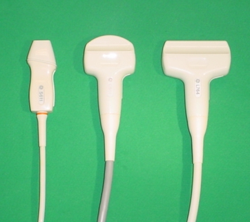
A key in the housing lets the head go on one way only. The shape of the shell guides the head into place and blocks a misfit, so a clinician in a hurry cannot seat it crooked or force a wrong head into the slot. The key carries the orientation the software counts on, since an array rotated even slightly would map the image to the wrong side of the screen.
A latch then holds the seated head against the pull of the cable and the knocks of a working shift. The catch clicks home with a feel a clinician learns to trust, a confirmation the contacts have met. The hold has to be firm enough that a tug on the cable does not lift the head, light enough that a deliberate release frees it in a second. That balance is tuned in the spring of the catch.
Alignment is the quiet half of the mechanical job. The array sits behind an acoustic lens aimed down a precise axis, so the housing has to land the head on that axis every time, within a fraction of a millimetre, or the focus drifts off where the software expects it. The same seat is repeated across thousands of swaps without wearing loose, which is why the locating faces are built of hard, low-wear material rather than the softer shell around them.
The insertion takes a measured force, tuned in the spring of the contacts and the bevel of the shell so the head slides home and clicks with a firm, repeatable feel. A clinician learns that feel and trusts it as the sign the join has met. The force stays the same across the heads in a family, so the hand expects one motion whichever head it reaches for.
The tolerance of the seat is held tight across the whole run of heads. Any head in the family lands on the same axis on any base in the fleet, so a clinician reads the same calibrated geometry whichever head and body are paired. That interchangeability is a manufacturing discipline as much as a design one, every head and every base machined to meet at the same plane to the same fraction of a millimetre.
Carrying the signal across the join
The electrical contacts are the heart of the connector, and they are where the engineering runs deepest. Each contact is a small spring that wipes against its mate as the head seats, a self-cleaning action that breaks through any film and lands a low-resistance path. The number of contacts runs from a few dozen to well over a hundred, set by how much of the array electronics rides in the head. A contact that sits a touch proud or a touch shy of its neighbours reads a weaker signal on that channel, so the grid is machined flat and sprung evenly, every pin meeting its pad with the same force. The signals these pins carry are faint and fast, the returning echoes of megahertz sound turned into millivolt traces, so the join guards them the way a good cable does. The contacts sit close together, which invites crosstalk, one channel’s signal leaking into the next, so the ground pins are laced through the grid to fence each live pin from its neighbour. The impedance of the path is held steady across the join, since a step in impedance bounces part of the signal back as an echo of its own that muddies the trace. A shield wraps the bundle against the electrical noise of a busy room, the hum of motors and lights and radios that would otherwise paint a haze across a faint return. The contacts are gold over a springy base metal, gold because it does not grow the oxide film that a cheaper metal would, the film that would raise the resistance of the join a little more with every passing week. All of this serves one end: the signal that leaves the head has to reach the beam-former as the same signal, since the image is only as honest as the weakest channel crossing the join. A single dead pin shows on the screen as a dim stripe down the picture, the dropout of one scan line, which is why the contact grid is the part a maker tests hardest and a buyer checks first on a used system. The join that carries the signal cleanly is invisible in the image. The join that does not announces itself in every frame.
Sealing the join against the clinical day
A probe lives in fluid: gel, the wipe of a disinfectant cloth, sometimes a full immersion soak for a sterile field. The connector has to keep all of it out of the contacts. A gasket around the seated join closes the gap between head and base, so the wipe runs over a sealed seam and reaches no live metal. The grade of that seal is written as an ingress rating, the figure a buyer reads to know whether the join survives a soak or only a wipe. The smooth outer shell carries no crevice for fluid to creep into, so the same surface that seals also cleans fast between patients, a plain gain on a busy list.
Telling the base which head is on
The base has to know which head it is driving, since a linear head and a convex head need different drive voltages, different frequencies, different presets. A code built into the head carries that identity, read through dedicated pins or a small memory chip the moment the head seats. The base reads the code and loads the matching preset before the first sweep, with no manual switch for a clinician to forget. The same memory often holds the head’s own calibration, the fine corrections measured for that individual array at the factory, so a head carries its character with it onto any base in the fleet.
That per-head memory is a quiet piece of engineering with a real clinical payoff. A head that drifts over time is recalibrated on its own and carries the new correction in its chip, leaving the rest of the kit untouched. A base that is replaced reads each head’s stored calibration afresh, so the fleet keeps working without a recalibration of every head. The identity the connector carries turns a bag of heads into a system that configures itself.
The preset arrives with the head
The clinician feels none of this. A head clicks on, the screen settles into the right depth and frequency, the scan begins.
Wear across a working life
The join is the one part of an interchangeable system that moves, so it is the part that wears. Every swap drags the contacts across each other and works the latch, a small abrasion repeated thousands of times. The contact springs are rated for a cycle count, the number of mate-and-unmate actions before the wipe force drops below what a clean signal needs. A maker publishes that count, and a heavy service tracks its swaps against it.
The locating faces wear on a slower clock than the contacts. Each seat drags the hard faces a little, loosening the fit over years rather than months, a play that a periodic check for wobble catches before it shifts the array off its axis. A worn head is replaced on its own, the base and the other heads carrying on, since the modular join localises the wear to the one part that moved.
The cable that runs from the connector to the base carries its own wear, flexing at the strain relief with every scan, so a well-built join moulds the cable into the shell gradually, not at a sharp edge that would crack the wire inside. A handheld that streams to a phone over a wireless link sheds the cable entirely, moving the only join to the one between head and body, which is part of why the wireless design leans so hard on the connector being right.
A service folds the connector into its routine. A quick look for bent or darkened contacts, a tug to feel the latch hold, a wipe to confirm the gasket still seals, each takes a moment between cases and keeps the join ahead of a failure that would pull a head from service mid-shift. A buyer reading a used system inspects the same things first, since the most-worked part of an interchangeable probe is the one that shows its age soonest.
Where the connector design shows its worth
A service that runs many heads on one base reaches its whole imaging range through this junction every working day. A keyed, latched, sealed connector with a clean contact grid lets a clinician swap a convex head for a linear one in seconds, trust the image that follows, and clean the device between patients without a thought for the join. The engineering disappears into the work, which is the mark of a connector designed right.
A buyer weighing an interchangeable handheld reads the connector as closely as the image. The contact count and the cycle rating say how the join will hold up. The ingress rating says how it cleans. The keying and the latch say how fast and how surely a head goes on. A device whose connector is built for the swaps a service will put it through is one that keeps its picture clean across the years the heads come and go.
Common questions about the interchangeable probe connector
What does the connector on an interchangeable probe do?
It carries the electrical signal between head and base, holds the head in mechanical alignment, identifies which head is fitted so the base loads the right preset, and seals the join against fluid. Four jobs in one small housing.
Why does the contact grid matter so much?
Each contact carries one channel of the array’s faint, fast signal. A pin that meets its pad weakly reads that channel low, and a dead pin shows as a dim stripe down the image, so the grid is machined flat and sprung evenly, every pin meeting with the same force.
How does the connector keep the signal clean?
Ground pins are laced through the grid to fence each live pin from crosstalk, the path impedance is held steady to stop internal echoes, a shield wraps the bundle against room noise, and the contacts are gold to resist the oxide film that would raise resistance over time.
How is the head held in alignment?
A key lets the head go on one way only, a latch holds it against the pull of the cable, and hard locating faces land the array on its precise axis within a fraction of a millimetre, repeated across thousands of swaps without wearing loose.
How does the base know which head is fitted?
A code or a small memory chip in the head is read the moment it seats, so the base loads the matching drive settings and preset with no manual switch. The same memory often holds that head’s own factory calibration.
Does the connector wear out?
It is the one moving part, so it wears. The contact springs are rated for a cycle count of mate-and-unmate actions, the locating faces can loosen, and the gasket ages. A worn head is replaced on its own, the base and other heads carrying on.

About the Author
Julien Mercier
Senior R&D Engineer · Medical Ultrasound Transducer Development
Senior R&D Engineer with an M.S. in Applied Physics and over 15 years of experience in medical ultrasound transducer development, specializing in the design verification and performance testing of high-frequency imaging transducers. Currently leading the development and verification of the company’s next-generation high-frequency linear-array transducer, responsible for imaging performance evaluation and reliability analysis in preclinical testing. Brings extensive hands-on experience in piezoelectric element tuning, beamforming parameter optimization, and system-level performance testing.