What is a Prismatic Cell in a Lithium Battery?
Prismatic cell means the battery goes in a rectangular aluminum or steel box. Same cathode, anode, separator, electrolyte as any lithium-ion cell, just arranged flat instead of rolled into a cylinder.
SNE Research puts prismatic at about 43% of global lithium-ion shipments in 2024. The share has been climbing since 2020 when Chinese manufacturers started scaling Cell-to-Pack architectures where the rectangular geometry pays off.
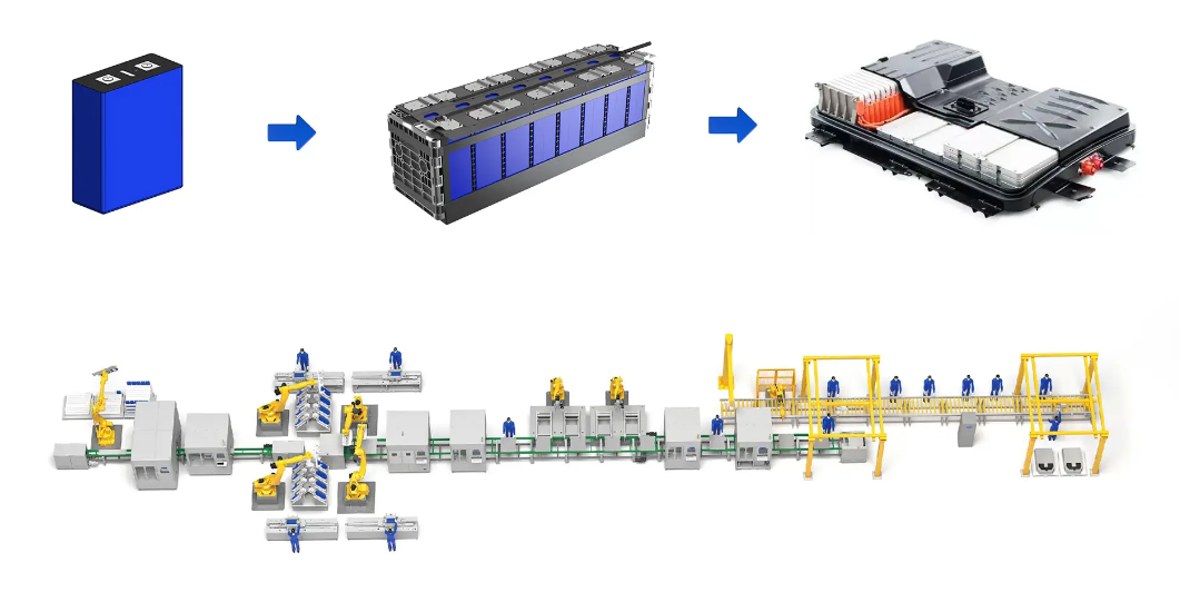
Modern EV battery pack assembly featuring prismatic cell configuration
Stacking vs Winding Matters More Than Cathode Chemistry
LFP or ternary, high-nickel or cobalt-free. Those matter. There's a more basic choice inside prismatic cells that gets less attention: whether the electrodes are wound or stacked.
Winding came from cylindrical cell heritage. You take continuous ribbons of cathode, separator, anode, roll them into an oval jelly roll, then flatten it to fit the rectangular housing. The equipment is mature. Throughput is high. Yields are predictable. Most prismatic cells on the market still use winding.
The problem shows up at the corners. When you flatten a rolled structure, the four corners have tight bend radii. The inner side of the bend gets compressed, the outer side gets stretched. Active material can crack or delaminate from the current collector. Current distribution isn't uniform either. The tightest radius at the core sees higher current density than the flat sections.
There's a 2021 PhD dissertation from RWTH Aachen, author named Simon Hein, that documented this with CT scans of aged cells. Corner regions showed clear lithium plating and electrode delamination after 1,500 cycles while the flat regions remained intact. The degradation localized right where you'd expect from the stress concentration.
Stacking cuts electrodes into individual sheets and alternates them with separator material. Every point on the stack sees identical geometry. Current distribution is uniform. Mechanical stress during cycling spreads evenly across the whole electrode area.
Fraunhofer IKTS ran a comparison study in 2022. Same materials, same coating parameters. Stacked cells came out 5-7% higher on energy density and about 15% longer on cycle life. They attributed it to the uniform current distribution and reduced mechanical stress concentration.
Stacking used to be too slow. Early equipment from companies like Manz took 1.2 to 1.6 seconds per sheet. A production cell might have 50 to 100 electrode pairs. Just the stacking step alone would take several minutes per cell. That throughput couldn't support mass production economics.
The equipment has caught up now. CATL's equipment subsidiary and Wuxi Lead Intelligent make stackers that do 0.11 to 0.15 seconds per sheet with alignment accuracy under 0.3mm. New production lines increasingly specify stacking equipment.
BYD uses stacking for the Blade Battery. The extreme aspect ratio of that cell, 960mm long by 13.5mm thick, would be a disaster with wound construction. Corner regions would be too large a fraction of total electrode area. The stress concentrations would be severe. BYD's 2020 patents (CN111384451A and related filings) describe the stacking process and the thermal benefits of the thin geometry in detail.
My personal view is that wound construction is becoming a legacy technology. New platform development is shifting toward stacking. Old products will keep using wound construction because the process development investment is already sunk, but the trajectory is clear.
The Geometry Thing
Pack cylindrical cells together and you get gaps. About 30% of the volume ends up as dead space filled with structural material or cooling channels. The 4680 format improves on smaller cylindrical cells in surface-to-volume ratio, but you can't escape the basic geometric penalty of circles.
Rectangular cells tile without gaps. Conventional module designs get to 80%+ space utilization. Cell-to-Pack configurations that skip the module layer push past 90%.
CATL's Qilin battery, announced in 2022, ran cooling channels between cells instead of under modules and got pack-level volume utilization to 72%. At the China EV100 Forum technical presentation in 2023, they showed 255 Wh/kg at pack level for the ternary version, 160 Wh/kg for LFP. Those numbers would be hard to reach with cylindrical formats.

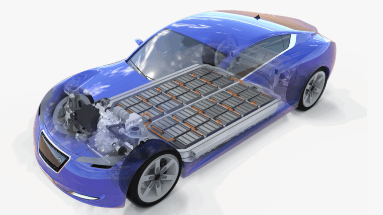
Electric vehicles increasingly rely on prismatic cell technology for optimal energy density
Tesla tells the story. They built the company on cylindrical cells. 18650s from Panasonic, then 2170s, now 4680s. The China-made Model 3 Standard Range uses CATL prismatic LFP. Not an ideology shift. The prismatic pack fit that vehicle architecture better and cost less per kilowatt-hour for that application.
BMW went prismatic with the i3 in 2013 and stayed there through iX and i7. Samsung SDI has been supplying them from production lines in Korea, Hungary, and the US. Partnership running over a decade with no sign of format change.
BYD designed their whole vehicle lineup around the prismatic Blade Battery starting 2020. The blade cells are structural members contributing to vehicle stiffness and crash protection. Switching to cylindrical would mean redesigning the platform from scratch.
What the Housing Does
The aluminum shell runs about 1.0 to 1.2mm thick according to teardown data from Munro & Associates. Mechanical protection is the first job. Cells in vehicles see constant vibration, thermal cycling from ambient temperature swings and charge-discharge heating, occasional impacts from road debris. The rigid housing absorbs those stresses.
The housing material choice depends on the application. Aluminum dominates in vehicles where every gram matters for range. Steel shows up in stationary storage where weight is secondary to cost. The price difference is meaningful at scale. Some manufacturers use aluminum-clad steel laminates trying to get mechanical properties closer to steel with weight closer to aluminum. Whether the complexity is worth it depends on production volume and price point.
Welded seams on the housing undergo helium leak testing during production. The test catches leaks too small to matter in the short term. Over years of service, even tiny leaks let moisture into the cell interior. Water reacts with the electrolyte salt to form hydrofluoric acid, which attacks the electrodes and accelerates degradation. Premium manufacturers target leak rates below 10^-9 mbar·L/s. Achieving that consistently requires tight process control on the welding equipment.
Pressure relief valves are set to open at 0.5 to 1.0 MPa depending on cell chemistry and capacity. The exact setpoint involves some engineering judgment. Too low and the valve opens during normal high-rate operation when some gassing is expected. Too high and you risk housing rupture before the valve activates. Overcharge, overheating, or internal defects generate gas. The valve vents it in a controlled direction instead of letting pressure build until the housing ruptures.
Pouch cells don't have this mechanism. Their aluminum laminate packaging swells and can burst unpredictably. The Hyundai Kona recall in 2020-2021 involved about 82,000 vehicles globally. Investigation reports cited separator damage and contamination in pouch cells leading to internal shorts and fires. The pouch format has real advantages in energy density, but the safety architecture requires more careful thermal management and cell-level monitoring to compensate for the lack of a rigid pressure vessel.
The flat exterior surfaces of prismatic cells mate well with cooling plates. Thermal interface material fills the microscopic gaps, creating a heat path from electrode stack to liquid cooling circuit. The interface material choice matters. Too thin and it doesn't fill surface irregularities. Too thick and thermal resistance increases. The material has to maintain its properties through years of thermal cycling without drying out or losing compliance. This is one of those details that sounds minor until you see field failures from bad thermal interface design.
Cylindrical cells only have line contact with cooling surfaces, which limits heat transfer. Tab cooling where the cooling fluid contacts the cell terminals works for low-power applications. High charge rates need better thermal paths than tab cooling provides. There's a 2023 paper from Tsinghua University in Journal of Power Sources (Vol. 556) that measured internal temperature gradients during 3C charging. Prismatic cells showed 8°C from center to surface. Cylindrical showed 15°C. Temperature non-uniformity causes non-uniform aging. The hotter regions degrade faster, eventually creating capacity imbalance within the cell that limits usable capacity even when plenty of active material remains.
LFP in Prismatic
LFP cathodes store about 170 mAh/g of specific capacity. High-nickel NMC811 stores 200-220 mAh/g. This energy density gap dominates most battery discussions and creates the impression that LFP is a budget compromise.
The impression misses cycle life. Good LFP cells reach 5,000 to 7,000 cycles. CATL's spec sheet for their 280Ah cell claims 6,000 cycles to 80% capacity at 25°C with 0.5C charge and discharge. High-nickel cells typically hit 1,500 to 2,500 cycles under similar conditions. The olivine structure is more stable than layered oxides. Less oxygen release at high state of charge means fewer side reactions eating into lithium inventory.
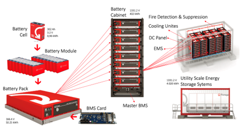
LFP battery technology supports the growing demand for sustainable energy storage
Run the total energy calculation. A cell that cycles 6,000 times, even at 80% of the capacity per cycle, delivers far more lifetime energy than a cell that only cycles 2,000 times. Storage applications with daily cycling strongly favor LFP. Vehicle applications expecting 15-year service life also favor LFP when you count total cost of ownership.
Thermal stability is another dimension. Sandia National Labs' 2019 abuse testing report showed LFP self-heating onset around 240°C versus 150-180°C for NMC chemistries. BYD's nail penetration videos from 2020 circulated widely. Steel nail through a Blade Battery cell, surface temperature hit about 60°C. Same test on ternary cells, thermal runaway within seconds, flames, temperatures past 500°C. The videos were marketing material. The underlying physics is well documented in peer-reviewed literature.
The prismatic format's space efficiency compensates for LFP's lower gravimetric energy density. At pack level, prismatic LFP often matches or exceeds cylindrical high-nickel once you account for module overhead, cooling system complexity, and structural requirements.
Cost has shifted hard toward LFP. No cobalt. No nickel. Iron and phosphate are globally abundant with diversified supply chains. LFP cathode powder dropped below $8/kg in China during 2024. NMC811 is still $25-30/kg. The raw material cost advantage has surpassed the energy density penalty for most applications.
High-nickel still has a place for premium vehicles competing on range specs, and for aircraft where weight directly limits payload. Consumer electronics favor high energy density given size constraints. These applications are a shrinking share of total battery demand.
The Other Components
The anode in nearly all prismatic cells is graphite coated on copper foil. Graphite has held this position for thirty years. Theoretical capacity is 372 mAh/g. Nothing that survives production at acceptable cost has exceeded it.
Silicon anodes promise dramatically higher capacity, around 4,200 mAh/g theoretical. The problem is silicon expands about 300% when it absorbs lithium during charging. The volume change cracks the electrode structure, exposes fresh surface to electrolyte that forms fresh SEI consuming lithium inventory, and causes rapid capacity loss. Silicon-graphite composites with 5-15% silicon content show up in some production cells, giving modest capacity gains while limiting the expansion problem. Pure silicon anodes remain a research topic. Every few years someone claims a breakthrough. Volume production keeps not happening.
The separator keeps the electrodes from touching while letting lithium ions pass through microscopic pores. It's a thin polymer membrane, around 20 micrometers in most designs. The material is usually polypropylene, polyethylene, or a trilayer combination. Trilayer separators sandwich polyethylene between polypropylene layers. The polyethylene melts at lower temperature than polypropylene, around 130°C versus 165°C. If the cell gets hot, the polyethylene layer softens first and closes its pores, shutting down ion transport. This thermal shutdown mechanism gives time for heat to dissipate before temperatures reach the point where the cell chemistry starts breaking down irreversibly.
Ceramic coatings on separators improve high-temperature performance and puncture resistance. Alumina or boehmite particles bonded to the polymer substrate raise the shrinkage onset temperature and provide a mechanical barrier against dendrites. Premium cells increasingly spec ceramic-coated separators. The cost is higher. Whether it's justified depends on the application's safety requirements and the overall thermal management architecture.
The electrolyte is lithium hexafluorophosphate salt dissolved in organic carbonates, usually some blend of ethylene carbonate, dimethyl carbonate, and ethyl methyl carbonate. The base formulation hasn't changed much in decades. The additives are where the proprietary magic happens.
Vinylene carbonate, typically 1-2% by weight, decomposes during first charge to form stable components of the SEI on the graphite anode. Fluoroethylene carbonate improves low-temperature performance and extends the voltage window before electrolyte breakdown. Flame retardant additives exist but they usually hurt ionic conductivity or cycle life. Every additive involves tradeoffs. The additive packages that distinguish premium cells from commodity products took years of formulation work and are treated as closely held trade secrets.
Coating and Formation
Coating is the step I've spent the most time on. It's the most critical part of the whole manufacturing process, and the one where accumulated know-how makes the biggest difference between a good manufacturer and a struggling one.
Slurry goes onto metal foil at 80-150 meters per minute. The slot-die coating head has to maintain thickness uniformity within 2 micrometers across a web width over one meter. That's an insanely tight tolerance at those speeds. The slurry is a shear-thinning fluid. Viscosity changes with shear rate, temperature, time since mixing. You mix a batch and the clock starts ticking. The slurry properties drift over hours. Coating head gap has to stay stable at the micrometer level despite vibration from other equipment in the facility. The foil is moving fast enough that small tension variations cause it to flutter. Drying has to remove solvent uniformly without creating temperature gradients that cause differential shrinkage, cracking, or curling at the edges.
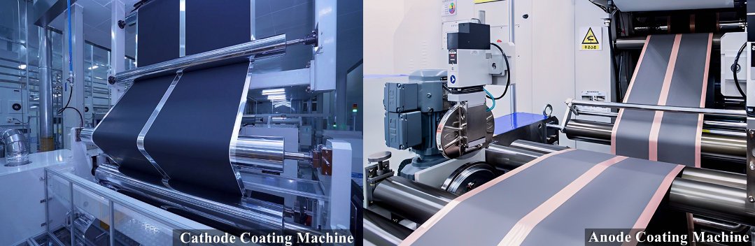
the coating and formation equipment in a battery manufacturing facility
The coating process has so many interacting variables that optimizing it takes months or years of systematic experimentation. Equipment vendors sell you the hardware. They don't sell you the recipes, the gap settings, the line speeds, the drying profiles that actually produce consistent coatings with your particular slurry formulation. That knowledge accumulates through production experience. A new market entrant buying identical coating equipment from the same vendor as an established manufacturer will not achieve the same results. This is why manufacturing quality advantage persists even when the equipment is commoditized.
There's a 2019 study from Karlsruhe Institute of Technology in the Journal of the Electrochemical Society that tracked the relationship between coating thickness variation and finished cell performance. Cells with variation above 3% showed faster impedance growth and faster capacity fade compared to cells below 1.5%. The thick spots limit charge rate because lithium ions have to diffuse further through the active material. The thin spots see higher current density and degrade faster than the rest of the electrode.
Edge quality matters as much as thickness uniformity. This is something that doesn't get discussed much in the literature but every production engineer worries about. Burrs or loose particles at electrode edges can puncture the separator during cell assembly or during cycling as electrodes expand and contract. Internal shorts from edge defects might not show up immediately. Cells can pass all initial testing, go into vehicles, and fail months or years later when the defect finally penetrates the separator completely. These are the failures that end up in recall campaigns and damage brand reputation.
Calendering compresses the dried coating to target density and porosity. The gap between calender rolls gets controlled to micrometer precision. Compress too much and you close pores that electrolyte needs to fill and ions need to move through. Compress too little and you leave void volume that reduces energy density and may create regions where electrolyte distribution is non-uniform.
Slitting cuts the wide electrode web into strips for specific cell designs. Edge quality at slitting is a whole additional challenge. Laser cutting gives you clean edges without mechanical burrs. Rotary knife cutting is faster and cheaper but the edge quality depends heavily on blade condition and cutting parameters. The choice between laser and mechanical slitting depends on quality requirements, production volume, and how often you're willing to change blades.
Formation takes three to five days. First charge builds the solid electrolyte interphase on the graphite anode. The SEI is this thin film, a few tens of nanometers thick, that forms from decomposition products of the electrolyte during initial charging. It has to conduct lithium ions while blocking electrons and solvent molecules. It has to stay stable through thousands of cycles as the graphite expands and contracts about 10% between full and empty states of charge. It can't keep growing indefinitely or it consumes lithium that you need for capacity.
SEI composition and morphology depend on charge rate, temperature, rest periods between charge steps, and the additives in your electrolyte formulation. A good SEI is thin, uniform, mechanically tough, and electrochemically stable. A bad SEI is thick, non-uniform, and keeps growing over the cell's lifetime. The difference shows up as capacity fade and impedance rise.
Formation protocols differ a lot between manufacturers and everyone treats them as core trade secrets. Samsung SDI patents describe multi-stage profiles with temperature ramping from 25°C to 45°C during initial charging, followed by extended high-temperature aging. CATL patents emphasize high-temperature aging steps after initial formation cycles, claiming improved SEI stability. LG patents mention applying pressure during formation to ensure uniform contact between electrodes and separator. Whether any of these approaches is actually better depends on the specific cell design and materials. There's no universal optimal formation protocol.
Formation also screens defective cells. Units with internal contamination or assembly defects show abnormal self-discharge during aging. The self-discharge test compares voltage drop over 7 to 14 days against the population distribution. Cells dropping voltage faster than the rest get rejected. Top manufacturers claim formation yields above 99%. The difference between 99% and 97% at production volumes measured in gigawatt-hours annually means 2 GWh of scrapped cells, worth several hundred million dollars at current prices.
The Blade Battery
BYD announced it in March 2020. The dimensions broke with convention. 960mm long versus typical prismatic cells at 150-300mm. 13.5mm thick versus typical 25-50mm.
The length lets single cells span across the battery compartment. Cells become structural beams providing stiffness. BYD eliminated module frames entirely. Cells attach directly to pack upper and lower plates with structural adhesive and mechanical fasteners. According to their published data, space utilization improved about 50% over conventional module designs. Pack-level volume utilization reached around 62%, up from 40% in their previous generation.
The thin profile keeps thermal gradients small. Maximum heat path from electrode center to cell surface is under 7mm. Temperature variation stays within a few degrees during normal operation. Compare that to thick conventional prismatic cells where center-to-surface distance can exceed 25mm and temperature gradients during fast charging become a serious design constraint.
Production ramp happened faster than outside observers expected. BYD shipped over 1.5 million vehicles with Blade Battery packs in 2023. The 2024 run rate exceeds 2 million. Vertical integration is a factor. BYD makes the LFP cathode material, manufactures the cells, assembles the packs, builds the vehicles. Coordination between stages doesn't require negotiating with external suppliers.
Competitors responded. CATL's Qilin battery uses similar structural integration concepts with different cell geometry, running cooling channels between cells rather than making cells into structural beams. Multiple Chinese manufacturers now offer blade-style cells for domestic and export markets. Structural integration has become standard for new platform development.
No Standardization
The 18650 cylindrical format dates to 1992. 18mm diameter, 65mm length. Equipment, testing protocols, secondary markets, regulatory frameworks all assume those dimensions. Tesla and Panasonic did the same when they adopted 21700 for Model 3.
Prismatic cells have no equivalent standard. Dimension combinations multiply with each new vehicle program. Length ranges from 150mm to over 900mm. Width from 90 to 200mm. Thickness from 12 to 70mm.
Each combination needs different manufacturing fixtures, different testing equipment, different pack designs. Cell inventory can't be shared between vehicle programs even within the same manufacturer. Second-life applications face a mess of incompatible formats when cells retire from vehicles.
VDA format in Europe provides some dimensional guidelines that German manufacturers partly follow. Chinese industry associations have proposed standard modules. Actual adoption is voluntary and incomplete. The installed base of non-standard cells already numbers in the hundreds of millions. Switching costs are high. Benefits from standardization only accrue as the installed base turns over. Individual manufacturers benefit from proprietary formats that lock in customers. The incentives don't align toward standardization.
Cell-Level Energy Density Gap
Cell-level numbers, prismatic runs lower than competing formats. Published specs show prismatic LFP at 160-180 Wh/kg, prismatic ternary at 200-240 Wh/kg, cylindrical high-nickel from Panasonic and LG over 260 Wh/kg, high-end pouch cells reaching 280-300 Wh/kg.
The rigid housing consumes volume and mass that flexible or cylindrical packaging uses more efficiently. Housing weight penalty runs 10-15% of total cell mass depending on design.
The future of battery technology continues to evolve as manufacturers balance energy density with practical considerations
Pack-level energy density closes the gap because prismatic cells pack more efficiently and may need simpler thermal management. For applications where pack volume is the hard constraint and gravimetric density is secondary, prismatic often comes out ahead.