What Does a Battery Module Do?
The module makes cells usable. Cells store energy well and do everything else poorly. They cannot survive mechanical stress. They overheat under load. They drift apart electrically and stay drifted. They burn when abused. The module addresses each of these problems.
Thermal management and safety containment dominate module engineering today. Electrical integration is solved. Mechanical protection is straightforward. Sensing uses commodity electronics. Keeping cells cool enough to survive fast charging, and preventing a single cell failure from cascading through an entire pack, consumes the majority of design effort and the majority of the bill of materials. This was not always the case. Fifteen years ago, electrical integration received more attention. The shift reflects both improved understanding of failure modes and regulatory pressure that continues intensifying.
Electrical Integration
Cells produce 3.2 to 4.2 volts depending on chemistry and state of charge. Applications need hundreds or thousands of volts. A single cell cannot power a vehicle or a grid storage installation. Multiple cells must connect together.
Series connections add voltage. Ten cells in series produce ten times the voltage of one cell. Parallel connections add capacity. Ten cells in parallel store ten times the energy of one cell. Every module combines both arrangements.
The sequencing question shaped module architecture for the entire industry. Should cells connect in series first, with those strings then connected in parallel? Or parallel first, with those groups then connected in series? The answer is parallel-first, and the reasons have compounded over decades of production experience.
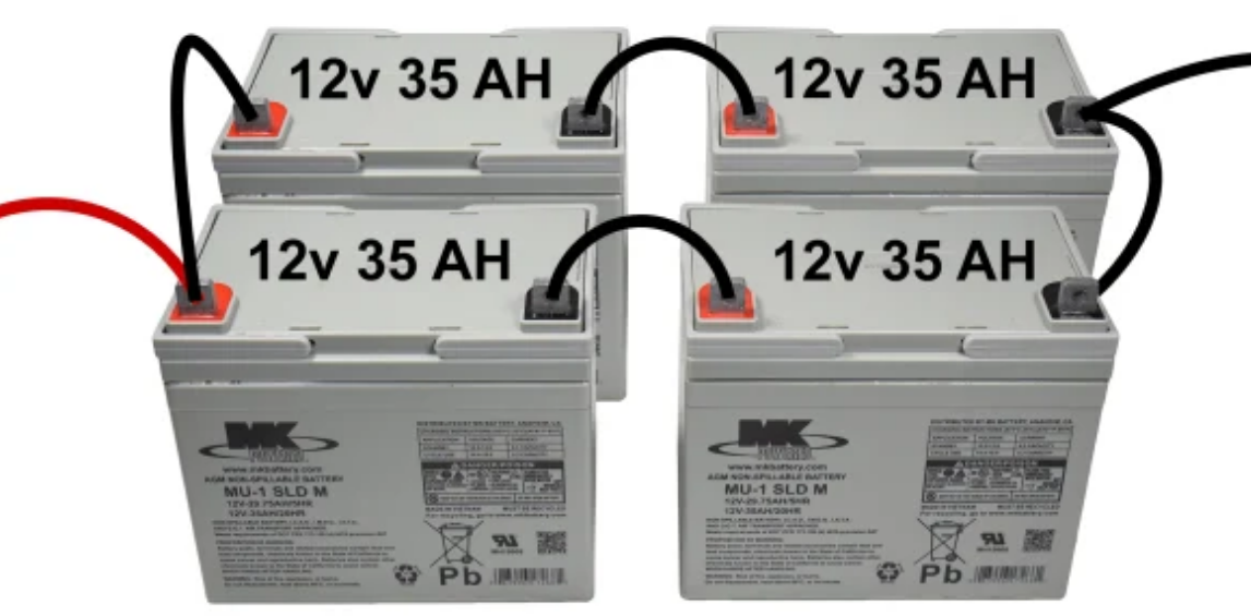
Parallel-connected cells self-balance through internal current flow. When cells in a parallel group have slightly different voltages, current flows from higher to lower until equilibrium. This happens automatically, continuously, without BMS intervention. The balancing requires no circuitry, consumes no energy beyond resistive losses during current flow, and introduces no failure modes.
Series-connected cells do not self-balance. A series string with one cell at 4.1 volts and another at 3.9 volts stays that way until external balancing circuitry intervenes. That circuitry adds cost, complexity, and failure modes.
The failure mode asymmetry matters more than the balancing behavior. A cell that fails open-circuit in a parallel group removes itself from the circuit. Current routes through the remaining cells. Capacity decreases proportionally. The group continues functioning. A cell that fails open-circuit in a series string breaks the string entirely. No current flows. The entire string goes dead. For products that must operate reliably for ten years, this asymmetry determines the architecture.
The Tesla Model 3 pack configuration became a reference design. Ninety-six series groups, each containing forty-six cells in parallel, totaling 4,416 cylindrical cells. The notation 96S46P encodes this structure. Ninety-six series groups at 3.7 volts nominal yields approximately 355 volts pack voltage. Forty-six parallel cells per group provides the capacity for roughly 78 kilowatt-hours total energy. Four physical modules divide this total: 23S, 25S, 25S, and 23S configurations.
Other manufacturers reach similar voltage and capacity through different specific configurations. The numbers vary. The parallel-first architecture does not. Pouch cells, prismatic cells, cylindrical cells of various diameters all integrate the same way. Cell format affects module geometry and assembly methods. Electrical architecture stays constant across formats.
The 800-volt platforms entering production double the series count to approximately 192 groups. Pack voltage rises. Charging current at equivalent power drops by half. Cable diameters shrink. Resistive losses decrease. Module design philosophy remains unchanged.
Thermal Management
The thermal function determines what a battery system can do versus what specifications claim it can do.
Cells generate heat during operation. Resistive losses in current collectors and electrolyte produce heat proportional to current squared. Electrochemical reactions produce or absorb heat depending on direction and state of charge. Concentration gradients within cells produce additional thermal effects. At low power levels, natural convection removes heat adequately. At high power levels, heat generation exceeds removal capacity. Temperature rises. Performance degrades. Aging accelerates. Safety margins erode.
The acceptable temperature range is narrow. Lithium-ion cells perform optimally between 20 and 35 degrees Celsius. Below zero, capacity drops substantially and charging becomes hazardous because lithium plates onto the anode surface rather than intercalating properly. This plating is irreversible and reduces capacity permanently while creating internal structures that can eventually cause short circuits. Above 45 degrees, calendar aging accelerates. Above 55 degrees, cycle aging accelerates further. Thermal runaway initiates around 130 degrees. The span between normal operation and catastrophic failure is perhaps 80 degrees. During fast charging at 350 kW, cells can heat 20 or 30 degrees in minutes if cooling is inadequate.
Temperature uniformity matters as much as absolute temperature. Cells in different positions within a module experience different thermal environments. Center cells sit surrounded by other heat-generating cells with limited access to cooling. Edge cells contact the enclosure and cooling system directly. Coolant enters at one temperature and exits warmer after absorbing heat from cells along its path. Cells near the coolant inlet stay cooler than cells near the outlet. These gradients mean some cells run hotter than others throughout their service life. Hotter cells age faster. Their capacity fades and internal resistance grows more rapidly than cooler neighbors. The pack becomes limited by its most degraded cells regardless of how healthy the majority remain.
Air cooling cannot address these problems at modern performance levels. Heat transfer coefficients for forced air convection reach perhaps 50 to 100 W/m²K under favorable conditions. This limits heat removal rates to levels adequate for low-power applications. Temperature gradients across air-cooled packs routinely exceed 15 degrees. Some cells age at three times the rate of others in the same pack. Air cooling works for golf carts, forklifts, residential storage systems charged and discharged once daily, and other applications with modest thermal loads. Passenger vehicles with fast charging capability abandoned air cooling years ago.
Liquid cooling extends capability substantially. Glycol-water mixtures flowing through aluminum cold plates or tubes achieve heat transfer coefficients of 500 to 2000 W/m²K. This order of magnitude improvement enables heat removal rates sufficient for fast charging. Temperature gradients compress to a few degrees. Cells age at similar rates. Pack longevity improves.
The implementation geometry shapes the entire module design. This point deserves emphasis because it explains why modules from different manufacturers look so different even when using similar cells.
Cold plate cooling places a thermally conductive plate beneath the cell array. Heat flows from cells downward through their bases, through a thermal interface material, through the cold plate, and into the coolant circulating within. This approach requires cells mounted with their bases in contact with the plate. Cylindrical cells can orient vertically with bases down. Prismatic cells can mount with their largest face against the plate.
Serpentine tube cooling routes coolant through tubes winding between cell rows. Heat flows from cell sidewalls into the tubes. This approach requires cells arranged with sidewall access for tube contact. Cylindrical cells work well because their curved surfaces nest against round tubes. The Tesla Model 3 and Model Y use this approach, with tubes contacting the sides of vertically-oriented cylindrical cells.
Between-cell cooling places cooling surfaces in the gaps between adjacent cells. Heat flows from both major faces of each cell into cooling elements on either side. CATL's Qilin battery uses this configuration. Thermal performance improves because heat extraction happens from two surfaces rather than one. The manufacturing complexity increases because cooling elements must integrate throughout the cell array rather than concentrating at one surface. The density decreases because gaps between cells consume volume that could otherwise contain active material.
Each thermal approach creates geometric constraints that propagate through the module design. Cell orientation, cell spacing, structural elements, electrical connections, and enclosure geometry all must accommodate the thermal strategy. A module designed for cold plate cooling cannot easily adapt to serpentine tube cooling. The thermal choice comes first and constrains everything else.
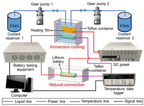
Immersion cooling submerges cells directly in dielectric fluid. Heat transfers from cell surfaces into surrounding fluid without intermediate materials. Thermal performance exceeds other approaches. Temperature uniformity improves because fluid circulation distributes heat throughout the volume. Thermal runaway propagation becomes difficult because fluid surrounding a failing cell absorbs heat and carries it away faster than conduction through solid materials.
The engineering challenges are substantial. Sealing an entire pack against fluid leakage requires different gasket materials, different fitting designs, different assembly and test procedures than conventional approaches. The dielectric fluids cost money and add mass. Compatibility between fluid and cell materials requires validation across temperature cycles, aging, and potential contamination scenarios that span years of testing. Fluid circulation systems add pumps, filters, and heat exchangers beyond those required for conventional liquid cooling.
Racing applications and some heavy-duty vehicles use immersion cooling. The performance advantages justify the added complexity and cost. Passenger vehicles have not adopted immersion cooling broadly. The technology works. The business case remains narrow for mainstream applications.
Phase change materials absorb heat through melting. A solid material at 25 degrees absorbs heat as temperature rises, then absorbs additional heat at constant temperature while changing phase from solid to liquid. The latent heat of fusion provides thermal buffering without active cooling systems. The concept appears attractive for passive thermal management.
The thermal conductivity of most phase change materials limits their utility. Paraffins and salt hydrates commonly used as phase change materials have conductivities around 0.2 to 0.5 W/m·K. Heat transfers slowly from cell surfaces into the bulk material. Hot spots develop. The full thermal capacity of the material goes unused because heat cannot penetrate quickly enough.
Composite materials incorporating graphite or metal structures improve conductivity. These additives increase cost and reduce the fraction of volume occupied by active phase change material. The practical thermal capacity decreases even as transfer rates improve.
Once fully melted, phase change materials provide no further thermal buffering until they resolidify. A drive cycle that melts the material early leaves no reserve capacity for later thermal events. The material must resolidify between cycles, which requires either active cooling or sufficient rest time at low ambient temperatures.
Some module designs combine phase change materials with liquid cooling. The phase change component handles transient peaks while active cooling handles steady-state loads and resolidifies the phase change material between events. These hybrid systems work. They rarely outperform adequately-sized liquid cooling systems at equivalent cost.
Safety and Thermal Runaway Containment
The safety function grew from minor design consideration to primary constraint over the past decade. Regulatory tightening drove this shift. High-profile fire incidents accelerated it.
Thermal runaway in lithium-ion cells proceeds through a sequence that research has characterized thoroughly. The sequence begins with elevated temperature from some initiating cause: external heating, internal short circuit, overcharge, mechanical damage. Around 80 degrees Celsius, the solid electrolyte interphase layer on the anode surface begins decomposing. This layer forms during initial cell formation and protects the anode from direct contact with electrolyte. Its decomposition exposes reactive anode material.
Around 120 degrees, the anode reacts directly with electrolyte. This reaction generates heat and gaseous products. Pressure inside the cell increases. Around 130 degrees, the polyethylene or polypropylene separator melts. The separator normally prevents direct contact between anode and cathode. Its melting allows internal short circuits that discharge the cell rapidly, converting stored electrical energy to heat within seconds.
Around 180 degrees, the cathode material decomposes and releases oxygen. Cobalt-containing cathodes release more oxygen at lower temperatures than iron phosphate cathodes, which partially explains the safety advantage of LFP chemistry. The released oxygen supports combustion of electrolyte and other organic components.
Cell temperature exceeds 600 degrees. The casing ruptures. Flammable gases vent at high velocity. If an ignition source exists, fire follows. Adjacent cells receive heat through conduction, convection, and radiation. If adjacent cells reach initiation temperatures, they begin their own runaway sequences. The cascade can consume an entire pack.
The module serves as the primary barrier against propagation. The strategy is straightforward: absorb or deflect enough heat from a failing cell to keep adjacent cells below initiation temperatures long enough for the failing cell to exhaust its stored energy.
Aerogel materials provide the best thermal isolation commercially available for this application. Silica aerogels achieve thermal conductivity around 0.015 W/m·K, approaching the theoretical minimum for solid materials. Temperature tolerance exceeds 1000 degrees Celsius. A few millimeters of aerogel between cells can block propagation entirely if properly applied, absorbing and delaying heat transfer long enough for the failing cell to burn out before adjacent cells reach critical temperatures.
Testing protocols subject module designs to forced thermal runaway of single cells, then monitor adjacent cell temperatures and overall pack behavior. Designs using adequate aerogel barriers pass these tests with margin. The failed cell burns out. Adjacent cells remain below initiation temperatures. No propagation occurs.
Cost limits aerogel deployment. The material costs more per unit area than alternatives. High-performance vehicles, aircraft applications, and premium stationary storage systems use aerogel barriers. Mainstream passenger vehicles generally do not.
Mica sheets provide a cost-effective alternative. Thermal conductivity around 0.6 W/m·K is approximately forty times higher than aerogel, meaning heat transfers faster and barriers must be thicker to achieve equivalent protection. Temperature tolerance remains excellent at over 1000 degrees. Most production electric vehicles use mica sheets between cells rather than aerogel.
The protection mica provides meets current regulatory requirements in most markets. Whether it continues meeting requirements depends on how standards evolve and how cell energy densities change. Higher energy density cells release more energy during runaway. Standards that previously required five minutes without fire or explosion now require two hours in China under the revised GB 38031. Meeting the extended requirement with mica barriers of reasonable thickness is difficult. Meeting it without weight and cost penalties that compromise vehicle competitiveness is harder.
Venting systems manage the gases released during thermal runaway. A cell in runaway generates substantial gas volume that must exit the pack in controlled fashion. Uncontrolled rupture sprays hot gas and particles unpredictably. Controlled venting directs gas flow away from adjacent cells and away from vehicle occupants.
Two-stage venting has become standard practice. The first stage uses permeable membranes, typically expanded PTFE, that allow continuous pressure equalization during normal operation. Temperature changes cause pressure variations that the membrane accommodates without admitting liquid water or contaminants. The second stage uses burst disks that remain sealed during normal operation and open rapidly when pressure exceeds a threshold. During thermal runaway, gas generation exceeds membrane permeation capacity. Pressure rises. The burst disk opens. Gas exits through a designed flow path to designated outlets.
The flow path design requires attention. Gas exiting a burst disk is hot and potentially flammable. The path must route this gas away from other cells, away from vehicle occupants, and away from ignition sources. Integration with vehicle body structures and crash safety systems adds constraints. The pack cannot vent into the passenger compartment. It cannot vent into wheel wells where hot gas contacts brake components. It cannot vent through paths that crash damage might block.
Sensing and Battery Management
Modules house the sensors that battery management systems require. Voltage sensing uses analog front-end integrated circuits designed specifically for battery monitoring applications. The LTC6811 from Analog Devices and the BQ769x0 series from Texas Instruments represent common choices. These devices measure individual cell group voltages with accuracy around plus or minus 1 to 2 millivolts while providing galvanic isolation between the high-voltage battery stack and low-voltage control electronics. A single device typically monitors 12 to 18 channels. Multiple devices chain together for larger modules.
Temperature sensing uses NTC thermistors in almost all production applications. The technology is mature and inexpensive. Placement matters more than sensor selection. A thermistor pressed directly against a cell surface measures cell temperature. A thermistor mounted to a structural element near cells measures something between cell temperature and structure temperature depending on thermal paths. Most module designs use two thermistors positioned to capture the range of temperatures present rather than the spatial distribution.
Current sensing uses Hall effect devices or shunt resistors. Hall effect sensors provide galvanic isolation inherently and accommodate the full current range without power dissipation. Accuracy degrades at low currents. Shunt resistors provide better accuracy across the range but require isolation circuits and dissipate power proportional to current squared.
Cell balancing circuits reside at module level. Manufacturing variations and aging differences cause cells in a module to diverge in capacity and internal resistance over time. Without balancing, the weakest cell limits pack performance. The weakest cell reaches full charge first during charging, triggering charge termination while other cells remain partially empty. The weakest cell reaches empty first during discharge, triggering cutoff while other cells retain charge.
Passive balancing dissipates energy from higher-voltage cells through resistors. The approach is simple, inexpensive, and reliable. Balancing currents typically range from 50 to 200 milliamps. Correcting a significant imbalance takes hours. Energy dissipated amounts to perhaps one percent of throughput.
Active balancing transfers energy from higher-voltage cells to lower-voltage cells using inductors, capacitors, or transformer-coupled circuits. Energy recovery efficiency reaches 85 to 95 percent. Balancing speed increases because transferred current can exceed passive balancing limits. Usable capacity from packs with mismatched cells increases because less energy wastes during balancing.
Active balancing costs more. The circuits require additional components. Cost per cell rises from tens of cents to several dollars. For new packs with well-matched cells, the performance difference is modest. Passive balancing keeps well-matched cells well-matched. For packs with significant cell variation, whether from manufacturing tolerance or aging, active balancing recovers more usable capacity.
Second-life applications repurposing used automotive batteries for stationary storage present significant cell variation. Active balancing provides meaningful benefit in this context. New vehicles with new cells present minimal variation. The benefit of active balancing in new vehicles is proportionally smaller.
Mechanical Protection
Cells require mechanical support to survive the environments where battery packs operate. Vibration, shock, and potential crash loads exceed what cells can withstand unprotected. The module provides rigid mounting, distributes loads, and constrains cell movement.
Enclosure materials balance weight, strength, thermal conductivity, and cost. Aluminum alloys provide excellent thermal conductivity, good strength-to-weight ratio, and corrosion resistance. Premium vehicles use aluminum enclosures extensively. Steel provides adequate performance at lower cost with weight penalty. Commercial vehicles use more steel where weight matters less than economics. Plastic and composite materials appear in structural elements where electrical isolation or specific mechanical properties are required.
The busbar system connecting cells within modules uses copper or aluminum conductors depending on the balance between conductivity, weight, and cost. Copper provides highest conductivity. Aluminum provides adequate conductivity at lower weight and cost with larger cross-sectional area.
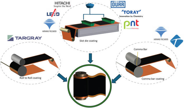
Laser welding dominates busbar-to-cell connections in production. The technique provides consistent, low-resistance joints with minimal heat input to surrounding cell components. Weld quality monitoring has evolved from post-production sampling to in-process sensing that tracks weld parameters in real time.
Cell expansion during charge and discharge cycles creates design constraints. A typical lithium-ion cell expands approximately 0.5 millimeters between empty and full states. A module containing 46 cells stacked in the expansion direction experiences cumulative expansion exceeding 20 millimeters. Module structures must accommodate this movement while maintaining thermal contact, electrical connections, and mechanical constraint. Spring-loaded compression systems allow expansion while maintaining consistent pressure. Rigid mounting systems that prevent expansion cause mechanical stress that damages cells over repeated cycling.
Cell-to-Pack Architectures
Cell-to-pack designs eliminate discrete modules as separate components, integrating cells directly into pack structures. BYD's Blade Battery uses elongated prismatic cells exceeding two meters in length that span the full pack width and contribute structural stiffness. CATL's Qilin battery integrates cooling elements between cells throughout the pack volume rather than within bounded modules. Tesla's structural pack in the Model Y bonds cells directly to upper and lower pack surfaces, using cells themselves as structural elements transferring loads between suspension attachment points.
These approaches increase volumetric efficiency. Traditional module-in-pack designs achieve 40 to 50 percent cell-to-pack volume ratio. CTP designs achieve 60 to 72 percent. The improvement translates directly to energy density at pack level. Part counts decrease by 40 percent or more compared to traditional approaches. Assembly processes simplify.
The functions that modules perform do not disappear when modules as discrete components disappear. Cells still require thermal management, safety containment, electrical integration, and sensing. CTP designs redistribute these functions throughout the pack structure rather than concentrating them within module boundaries. Cooling elements that previously belonged to modules now belong to the pack. Barriers that previously separated cells within modules now separate cells within packs. Sensing that previously occurred at module level now occurs at pack level with different wiring topology.
Serviceability changes substantially. Module replacement in traditional designs requires disconnecting electrical, thermal, and structural interfaces, removing the module, installing a replacement, and reconnecting. The process takes hours and requires moderate skill. Cell replacement in CTP designs ranges from difficult to impossible depending on specific design choices. A failed cell may require pack replacement rather than repair. Whether this matters depends on failure rates, warranty structures, and vehicle lifetime expectations that vary across markets and segments.
Summary
The battery module converts cells from laboratory components into functional energy storage systems. The module provides electrical integration that cells cannot provide for themselves, combining cells in series and parallel to reach application voltage and capacity requirements. The module provides thermal management that cells cannot provide for themselves, removing heat during operation and maintaining temperatures within acceptable ranges. The module provides safety containment that cells cannot provide for themselves, blocking thermal runaway propagation through barriers and venting. The module provides sensing that enables battery management, housing voltage, temperature, and current sensors plus balancing circuits.
The engineering weight among these functions has shifted over two decades. Electrical integration is mature. Mechanical protection is straightforward. Thermal management and safety containment now dominate design effort, reflecting both improved understanding of thermal behavior and regulatory requirements that continue tightening. Module engineering today is predominantly thermal and safety engineering.
Cell-to-pack architectures redistribute module functions without eliminating them. The functions persist whether implemented in discrete modules or integrated throughout pack structures. Understanding what a battery module does remains relevant as physical boundaries between module and pack dissolve in newer designs.