


How Do Battery Packs Lithium Work?
Your smartphone powers through an 18-hour workday. Electric vehicles travel 300 miles on a single charge. Power tools deliver consistent torque without cord limitations. Global lithium-ion battery pack production exceeded 1 terawatt-hour in 2024, and analysts project pack-level demand to reach $92.8 billion by 2035, though such forecasts deserve skepticism given the industry's history of overpromising.
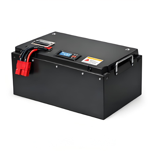
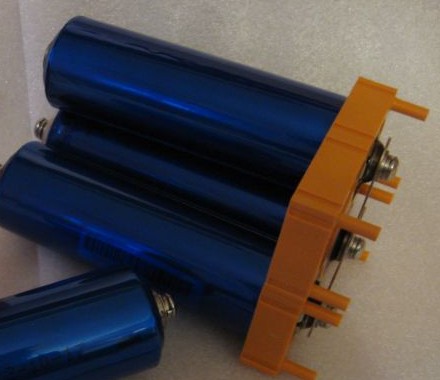
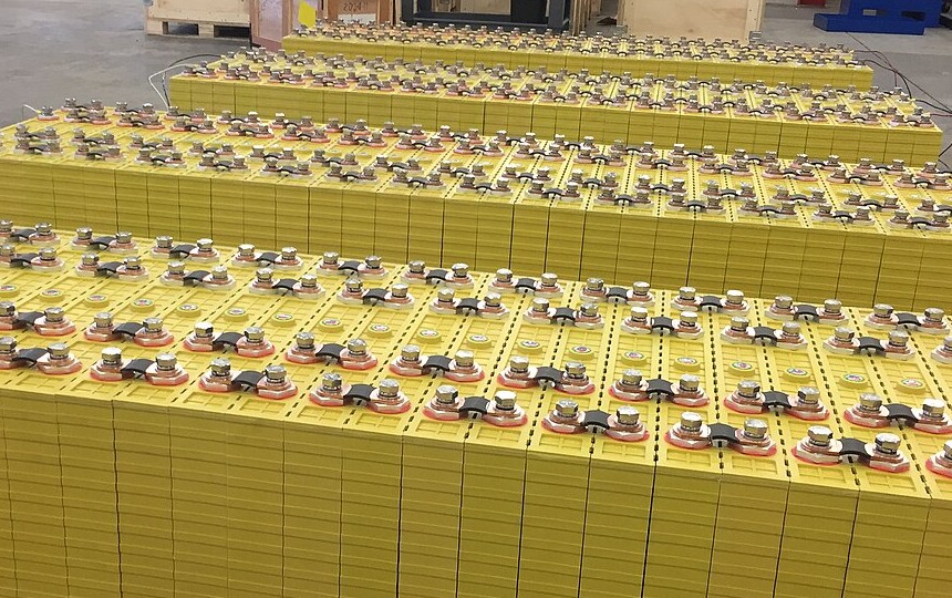
Modern lithium-ion battery cells form the foundation of portable power across industries
Power Behind Modern Devices
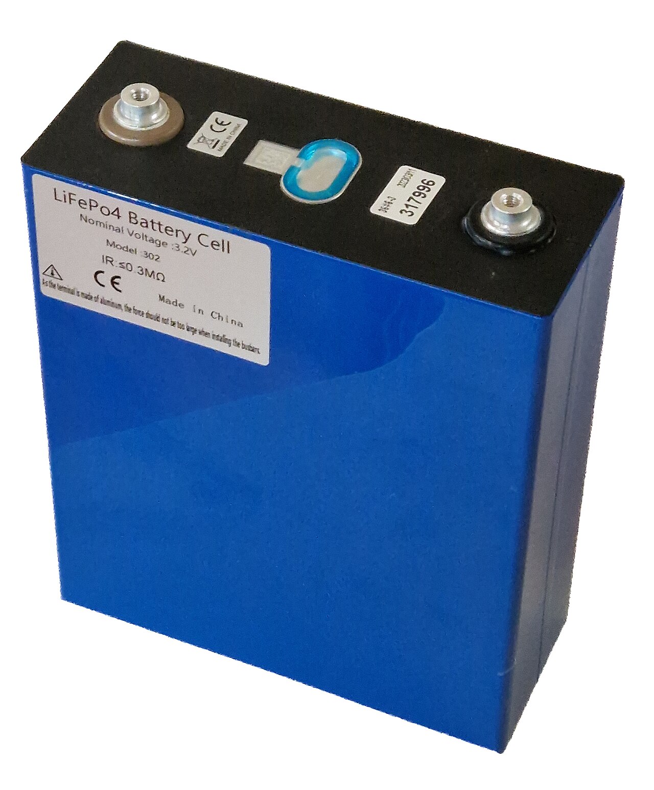
Battery packs lithium serve as the primary energy source across applications ranging from 3.7V smartphone batteries to 800V electric vehicle systems. The fundamental advantage stems from energy density. Lithium-ion chemistry stores 150-300 watt-hours per kilogram compared to 25 watt-hours for lead-acid alternatives, a gap that explains why nobody seriously proposes lead-acid smartphones. Recent manufacturer claims suggest energy densities now reaching 400 Wh/kg in advanced configurations, though such figures often reflect laboratory conditions rather than production reality, and the gap between press release and shipping product remains substantial.
Atomic properties give lithium chemistry its dominance. Lithium sits third on the periodic table with an atomic weight of just 6.94 g/mol, making it the lightest metal in existence. This low mass means each kilogram of lithium can store vastly more electrochemical energy than heavier alternatives like lead (207.2 g/mol) or nickel (58.7 g/mol). Combined with lithium's high electrochemical potential of -3.04V versus standard hydrogen electrode, the element offers an unmatched combination of lightweight construction and voltage output. Sodium-ion advocates tout abundance and cost advantages, but sodium's atomic weight of 22.99 g/mol imposes an energy density ceiling that physics cannot overcome. The periodic table does not negotiate.
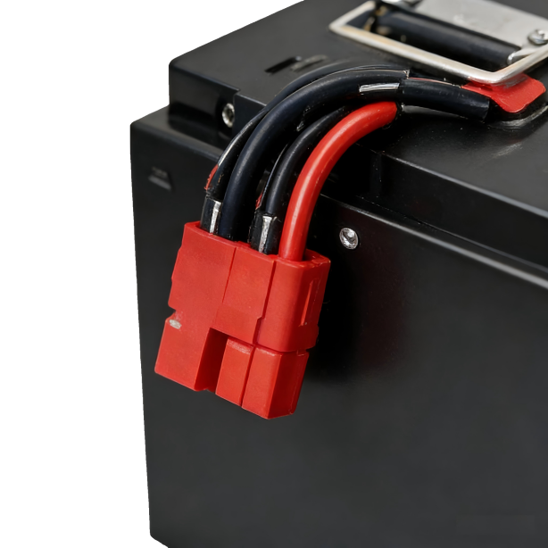
Electric vehicles rely on sophisticated lithium-ion battery packs delivering 75-100 kWh capacity
Tesla and other electric vehicle manufacturers pack thousands of individual cells into configurations delivering both high voltage (400-800V) and substantial capacity (75-100 kWh). Consumer electronics require different specifications. Laptops typically use 10.8V packs with 4000-6000mAh capacity, while power tools operate at 18-60V depending on torque requirements. Engineers scale voltage and capacity by adjusting cell count and connection patterns.
Industrial applications demonstrate another performance dimension. Forklift batteries now deliver 48V systems with 200-300Ah capacity, replacing lead-acid units while reducing weight by 60-70%. The weight reduction matters less for forklifts than for vehicles, but the reduced maintenance and longer cycle life justify the higher upfront cost for warehouse operators running multiple shifts. Solar energy storage installations use 48V modular packs that scale from 5kWh residential systems to multi-megawatt commercial arrays. This versatility explains why battery packs lithium captured 89% of the rechargeable battery market by late 2024.
Smartphone batteries prioritize energy density to minimize device thickness. The relentless pursuit of thinner phones has pushed cell designs toward configurations that maximize capacity per cubic centimeter, sometimes at the expense of longevity that users only notice two years after purchase. Electric vehicle packs balance energy density with power density to enable rapid acceleration while maintaining range. Grid storage systems emphasize cycle life, with modern LFP chemistry delivering 5,000+ charge-discharge cycles versus 800-1,000 for traditional lithium-ion variants.
Battery Pack Specifications Across Applications
| Application | Voltage | Capacity | Energy Density | Cycle Life | Weight |
|---|---|---|---|---|---|
| Smartphone | 3.7V | 3000-5000mAh | 250-300 Wh/kg | 500-800 | 40-60g |
| Laptop | 10.8-14.8V | 4000-6000mAh | 200-250 Wh/kg | 500-1000 | 300-400g |
| Power Tool | 18-60V | 2-9Ah | 180-220 Wh/kg | 1000-2000 | 500-1500g |
| EV | 400-800V | 75-100kWh | 250-400 Wh/kg | 1500-5000 | 400-600kg |
| Grid Storage | 48-800V | 10-100kWh | 160-200 Wh/kg | 5000-8000 | Varies |
Core Mechanism Explained
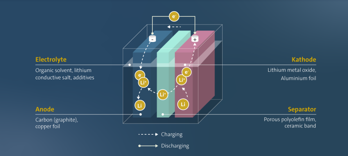
The basic operation works like this: lithium ions shuttle back and forth between two electrodes, and the direction of travel determines whether the cell charges or discharges. When a device draws power, ions leave the anode, pass through a liquid electrolyte, and arrive at the cathode. Electrons take a different path, flowing through the external circuit to do useful work. The elegance of this reversible reaction explains why lithium-ion technology displaced earlier rechargeable chemistries so completely.
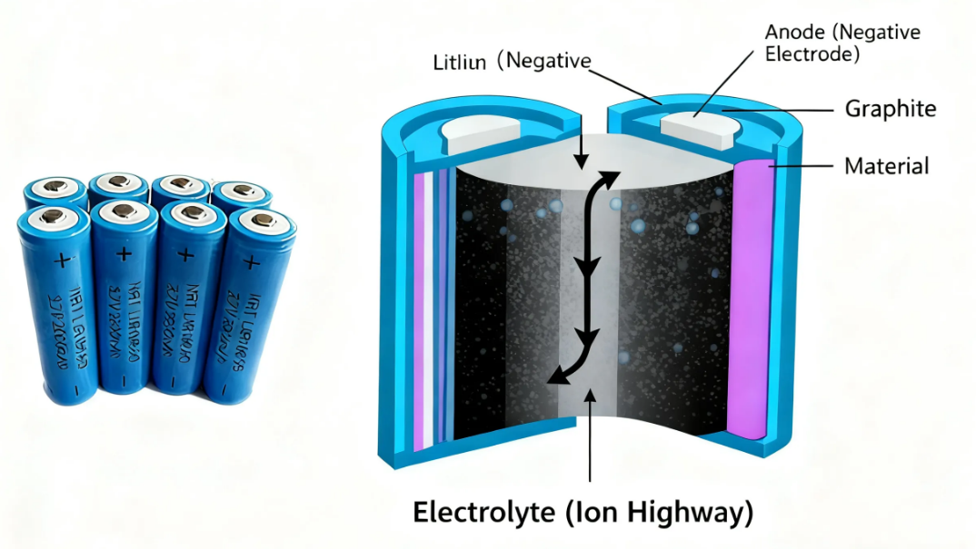
The internal structure of lithium-ion cells enables efficient energy storage and release
Graphite or silicon-enhanced materials form the anode, intercalating lithium ions within their crystalline structure. Graphite's layered hexagonal lattice creates galleries between carbon sheets where lithium ions nest during charging, achieving a theoretical capacity of 372 mAh/g. Modern silicon anodes increase energy capacity by 40% compared to pure graphite. Silicon's theoretical capacity reaches an extraordinary 4,200 mAh/g, a number that launched a thousand startup pitch decks. The practical problem is that silicon swells by approximately 300% when fully lithiated, creating mechanical stresses that fracture electrode structures and expose fresh surfaces to parasitic reactions with the electrolyte.
The industry spent a decade pursuing silicon anodes with the fervor of alchemists seeking gold. Pure silicon anodes failed catastrophically in early implementations. Within 50 cycles, capacity collapsed as the electrode literally pulverized itself. The current compromise blends 5-15% silicon or silicon oxide into graphite matrices, capturing perhaps 15% of silicon's theoretical advantage while managing expansion damage. Billions in R&D investment yielded incremental gains, and cycle life penalties persist in ways that manufacturers rarely highlight in their marketing materials. The pursuit of silicon exemplifies a broader pattern in the battery industry: theoretical limits make compelling investor presentations, but electrochemistry remains stubbornly indifferent to business plans.
The periodic table does not negotiate. Electrochemistry remains stubbornly indifferent to business plans.
Lithium cobalt oxide (LiCoO2) provides high energy density for consumer electronics, packing maximum capacity into minimum volume at the cost of thermal stability. This chemistry dominates smartphones precisely because consumer electronics manufacturers have calculated that thermal runaway incidents affecting one device in ten million represent acceptable risk when weighed against the competitive disadvantage of thicker phones. The calculation is rational but rarely articulated publicly, and the occasional exploding phone serves as a reminder that the margin for error remains thin.
Lithium iron phosphate (LiFePO4) offers superior safety and longevity for electric vehicles and stationary storage. The olivine crystal structure resists oxygen release during thermal abuse, eliminating the primary thermal runaway initiation mechanism. LFP's lower energy density (roughly 160 Wh/kg versus 250 Wh/kg for NMC) previously confined it to commercial vehicles and stationary storage where weight mattered less than safety and cost. The chemistry's recent resurgence in passenger EVs reflects a maturing industry. Tesla's shift to LFP for standard-range vehicles signals that the energy density race may have overshot what consumers actually need, creating products optimized for specification sheets rather than decade-long ownership.


Nickel-manganese-cobalt (NMC) chemistries in ratios like 811 (80% nickel, 10% manganese, 10% cobalt) balance energy density against stability, dominating the premium electric vehicle sector. The progression from NMC 111 to 532 to 622 to 811 traces the industry's systematic reduction of cobalt content. The technical motivation is real, since high-nickel cathodes do offer better energy density, but the urgency comes from elsewhere. Over 70% of global cobalt originates from the Democratic Republic of Congo, where artisanal mining operations employ child labor in conditions that have generated sustained international condemnation. The push toward high-nickel, low-cobalt formulations represents an attempt to engineer around a supply chain crisis rather than address it directly, and NMC 811's reduced cobalt content comes with reduced thermal stability. Whether this tradeoff serves consumers or merely insulates manufacturers from reputational risk depends on how one weighs the competing concerns.
The electrolyte medium enables ion transport between electrodes. Traditional liquid electrolytes use lithium salts, typically lithium hexafluorophosphate (LiPF6), dissolved in organic carbonate solvents like ethylene carbonate and dimethyl carbonate. Lithium ions move freely through this solution while electron flow remains blocked, preventing internal short circuits. However, these organic solvents remain flammable with flash points around 30°C, and decomposition products include hydrogen fluoride, a gas that causes severe chemical burns and attacks glass. This explains why battery fires prove so difficult to extinguish and why firefighters increasingly allow EV fires to burn themselves out rather than risk exposure. The industry prefers not to dwell on these details.
A microporous separator membrane, usually polyethylene or polypropylene films with sub-micron pores, physically isolates the anode and cathode while allowing ionic conduction. The separator stands as the cell's most critical safety component and its most underappreciated point of failure. Separator thickness has decreased from 25 micrometers to under 12 micrometers as manufacturers chase energy density. Thinner separators mean less inactive material and more space for electrodes. A contamination particle 15 micrometers across, smaller than a human hair's diameter, can puncture a 12-micrometer separator and initiate an internal short. The manufacturing cleanliness required to produce reliable thin separators approaches semiconductor fabrication standards, yet battery cells sell for dollars rather than the hundreds of dollars per chip that support semiconductor cleanroom investments. The economics create persistent tension between safety margins and cost targets.
Charging works in reverse. External voltage forces lithium ions to migrate from the cathode back to the anode, where they reinsert into the graphite or silicon structure. This process requires precise control. Charging lithium-ion cells above 4.2V per cell or below freezing temperatures can cause lithium plating, where metallic lithium deposits on the anode surface. This phenomenon reduces capacity and creates dendrite formations that may penetrate the separator and cause dangerous internal shorts.
Lithium plating at low temperatures causes permanent, irreversible damage that accumulates with each cold-weather charging session. A user who routinely charges an EV in a cold garage without preconditioning the battery may lose 20% of capacity within two years, then blame the manufacturer for "battery degradation" that their own behavior caused. The BMS in quality vehicles prevents charging below approximately 0°C, but many consumer electronics and lower-tier EVs implement this protection inadequately or not at all. The owner's manual warnings about cold-weather charging exist for reasons that become expensive to ignore.
Charge/Discharge Cycle Process
- Discharge Phase: Lithium ions move anode → cathode; electrons power load
- Voltage Drop: Cell voltage decreases from 4.2V to 3.0V cutoff
- Charge Phase: External voltage forces ions cathode → anode
- Constant Current: Charger supplies steady current until 4.2V reached
- Constant Voltage: Current tapers while maintaining 4.2V until fully charged
The Department of Energy notes that a single lithium-ion cell generates 3.7V nominal voltage, significantly higher than the 1.5V from alkaline AA cells. This voltage advantage allows manufacturers to use fewer cells in series to achieve target operating voltages, reducing pack complexity and potential failure points. Fewer connections means fewer opportunities for something to go wrong.
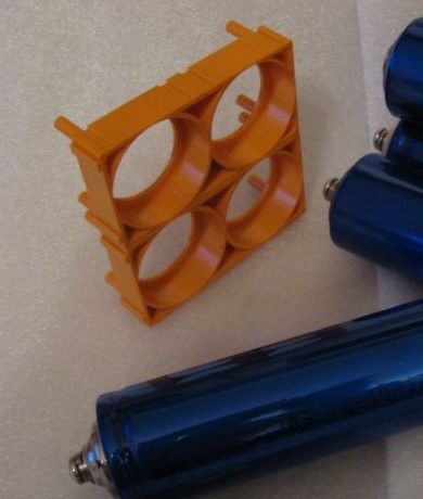
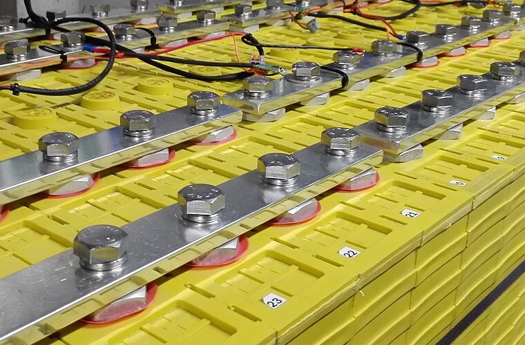
Pack Architecture and Configuration
Individual lithium-ion cells must connect in specific patterns to deliver required voltage and capacity specifications. Engineers use two fundamental connection methods: series and parallel arrangements. Series connections increase voltage while maintaining cell capacity. Four 3.7V cells in series (designated 4S) produce 14.8V nominal voltage. Parallel connections maintain voltage while adding capacities. Two 3000mAh cells in parallel (designated 2P) deliver 6000mAh total capacity.
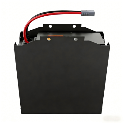
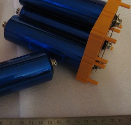
Complex battery packs combine series and parallel cell arrangements for optimal performance
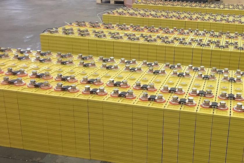
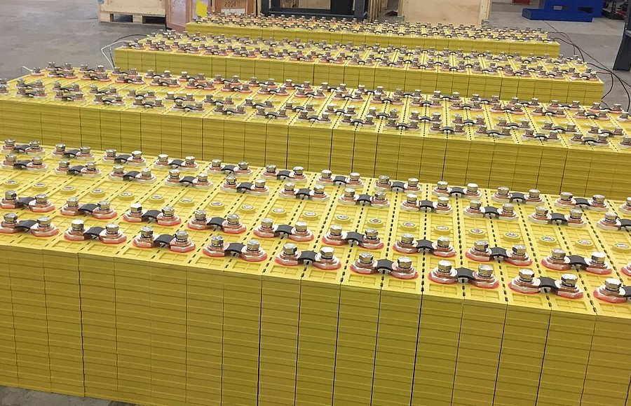
Complex battery packs combine both methods in configurations like 10S4P (10 cells series, 4 cells parallel) or 13S2P. Electric vehicle packs typically use hundreds or thousands of cells in mixed configurations. The Tesla Model 3 Long Range employs approximately 4,416 cylindrical 21700 cells arranged in modules, ultimately configured to deliver 350V nominal voltage with 82kWh capacity. This modular approach allows manufacturers to scale pack size while maintaining standardized cell production, though the sheer number of cells and connections creates quality control challenges that simpler designs avoid.
Three primary cell formats exist in commercial battery packs: cylindrical, prismatic, and pouch. Each format has entrenched manufacturing ecosystems and corporate champions that resist consolidation. This fragmentation imposes costs throughout the value chain. Pack designers cannot optimize for a single format. Recyclers must handle heterogeneous feedstocks. Second-life applications remain constrained by format incompatibility. The closest approach to standardization came from Tesla's popularization of the 2170 cylindrical format and subsequent 4680 development, emerging from a single company's supply chain leverage rather than industry cooperation. Standards bodies have tried and largely failed to impose order.
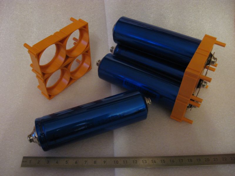
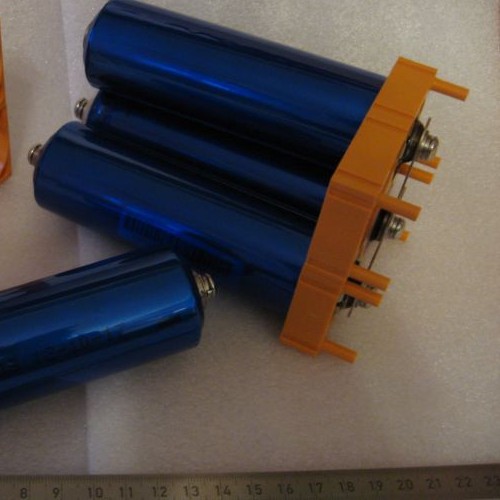
Cylindrical cells (18650, 21700 formats) dominate consumer electronics and power tools due to established manufacturing processes and robust mechanical structure. The cylindrical geometry distributes internal pressure uniformly, resisting the swelling forces that accompany charge cycles. Decades of manufacturing optimization have driven cylindrical cell costs below any alternative. The format wastes approximately 35% of pack volume in interstitial spaces between packed cylinders, a geometric inefficiency that matters enormously for applications where every cubic centimeter affects product viability.
Prismatic cells use flat rectangular housings that maximize volumetric efficiency in applications like electric vehicles where space constraints are severe. The prismatic format eliminates wasted interstitial space, achieving packing efficiencies above 90% compared to roughly 65% for cylindrical arrangements. However, prismatic cells require thicker aluminum housings to resist swelling forces that cylindrical geometry naturally distributes, partially offsetting volumetric gains with increased inactive material weight. The format also concentrates mechanical stress at corners and edges, creating fatigue failure initiation points that accumulate damage over thousands of charge cycles.
Pouch cells eliminate rigid casings entirely, achieving the highest gravimetric energy density but requiring external compression to prevent swelling during charge cycles. The aluminum-polymer laminate pouch adds minimal weight, perhaps 5% of cell mass versus 15-20% for cylindrical cans, but transfers structural requirements to the pack level. Pack-level compression systems add weight, complexity, and failure modes that cell-level specifications do not capture. A pouch cell's datasheet energy density overstates the achievable pack-level density by 15-25% once compression plates, thermal management interfaces, and structural reinforcement are included. Buyers comparing specifications across formats rarely account for this discrepancy, and manufacturers have little incentive to clarify.

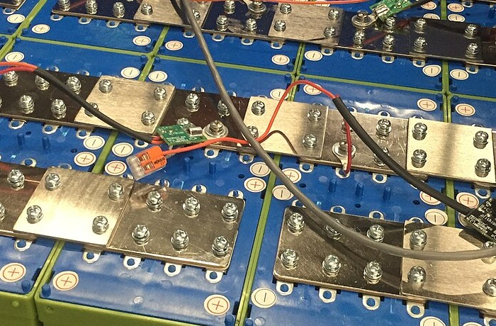
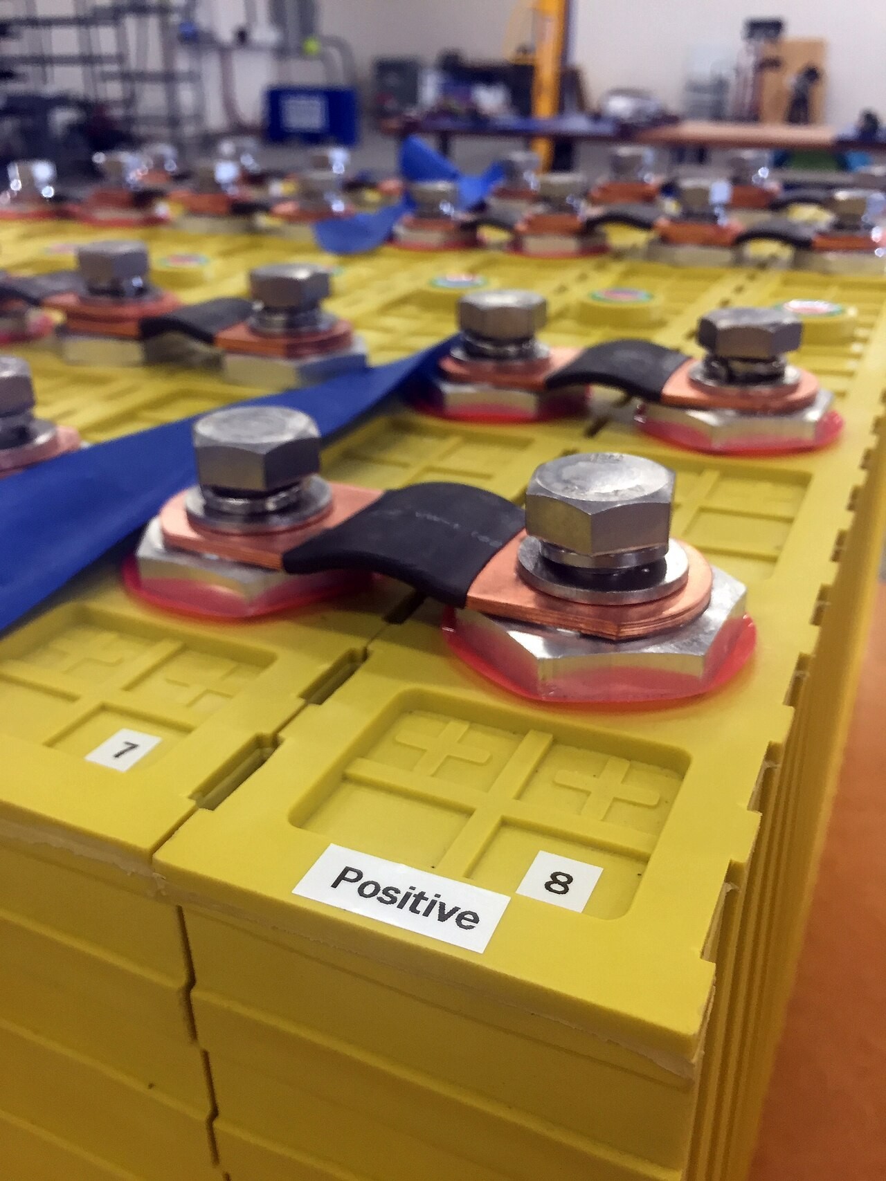
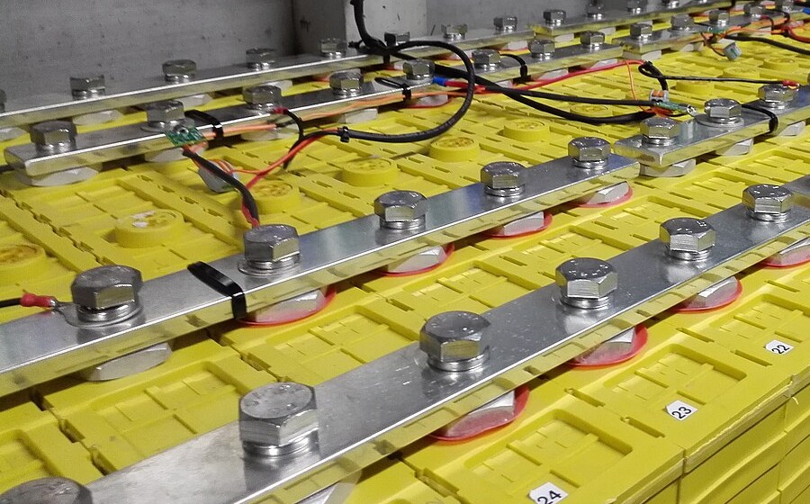
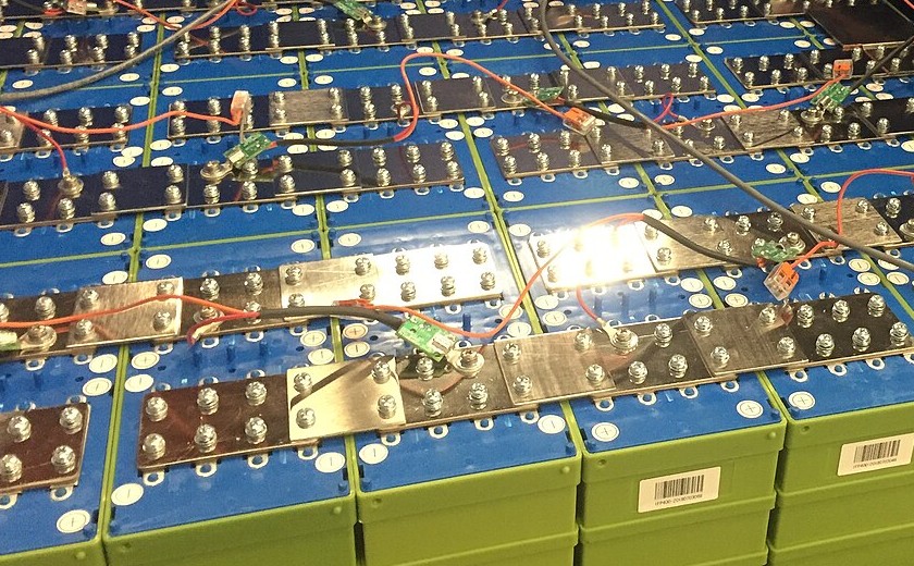
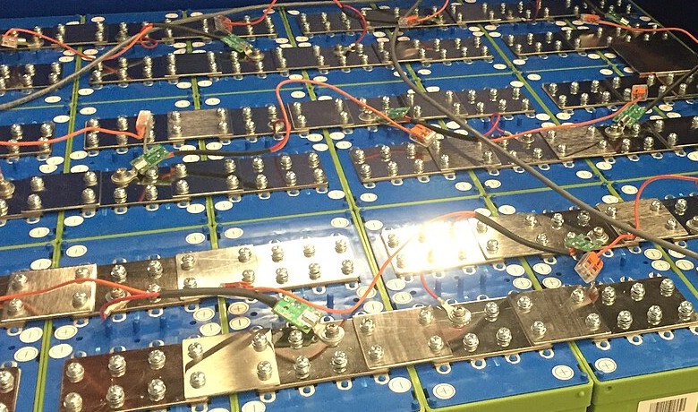
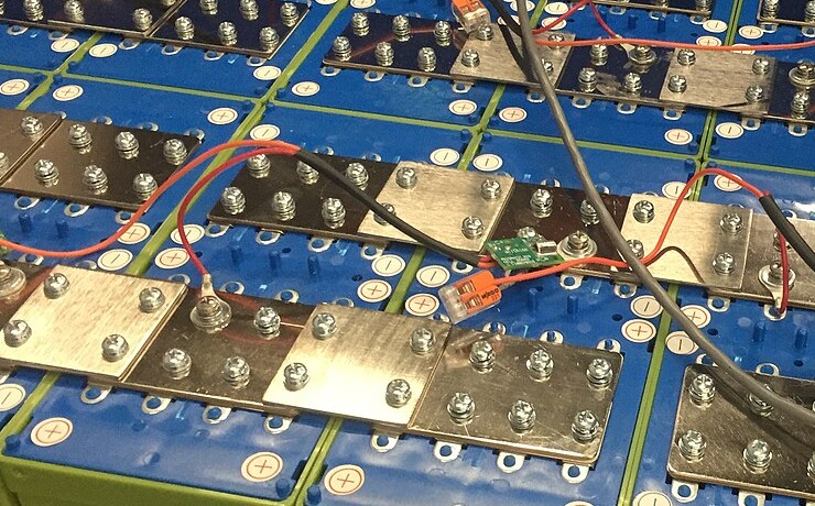
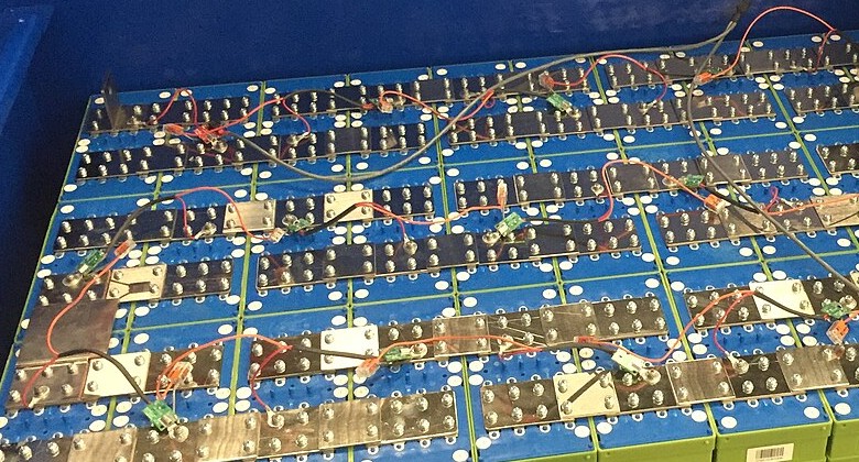
Bus bars, typically copper or aluminum conductors, connect cells within modules. These bars must handle substantial current flow (potentially 100-1000A in automotive applications) while resisting vibration and thermal expansion. Manufacturers use laser welding or ultrasonic bonding to attach bus bars to cell terminals, creating permanent connections that should maintain low contact resistance throughout the pack's operational life.
Connection quality separates premium packs from disposable ones, yet connection quality remains invisible to buyers and largely unaddressed by specifications. A cold solder joint or inadequate weld might pass initial quality inspection while harboring resistance that increases over thermal cycles. Within two years, that connection becomes a localized heat source that accelerates adjacent cell degradation and may eventually initiate thermal events. Battery teardown analyses reveal connection quality variation even within single manufacturer product lines, suggesting quality control systems that sample rather than inspect exhaustively. The consumer has no practical way to evaluate this before purchase.
Battery packs generate heat during both charging and discharging, with rates varying based on C-rate (charge/discharge rate relative to capacity). A 1C rate means discharging the full capacity in one hour; 2C discharges in 30 minutes. Higher C-rates generate more heat, potentially degrading performance and safety. Thermal management becomes critical as cell count increases and represents the domain where pack engineering most dramatically separates competent from incompetent implementations.
The relationship between temperature and degradation follows Arrhenius kinetics: reaction rates approximately double for every 10°C temperature increase. A cell operating at 45°C degrades roughly four times faster than one operating at 25°C. This exponential relationship means that thermal management quality compounds over ownership period. A pack that runs 10°C hotter than its competitor will reach 80% capacity in perhaps one-third the time. Thermal management systems add cost, weight, and complexity that consumers cannot evaluate at purchase, creating a market dynamic that rewards manufacturers who economize on invisible components. The consequences emerge years after warranty expiration, by which point the consumer has no recourse and the manufacturer faces no accountability.
Advanced packs incorporate cooling systems, either passive air cooling for lower-power applications or active liquid cooling for high-performance EVs, to maintain optimal operating temperature ranges between 20-30°C. Liquid cooling using glycol-water mixtures circulated through cold plates achieves heat removal rates impossible with air cooling, but introduces complexity. Pumps, hoses, heat exchangers, and the fluid itself all represent potential failure points. The industry has not solved liquid cooling system longevity. Ten-year-old EVs increasingly report cooling system failures that precede rather than follow battery degradation, suggesting that the weakest link in pack longevity may not be the cells themselves.
Series vs. Parallel Configuration Comparison
| Configuration | Voltage Effect | Capacity Effect | Use Case |
|---|---|---|---|
| Series (nS) | Multiplies by n | Unchanged | Increasing voltage for motor systems |
| Parallel (nP) | Unchanged | Multiplies by n | Extending runtime in fixed-voltage devices |
| Mixed (nSnP) | Both increase | Both increase | EV packs requiring high voltage and capacity |
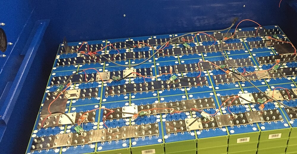
Battery Management Intelligence
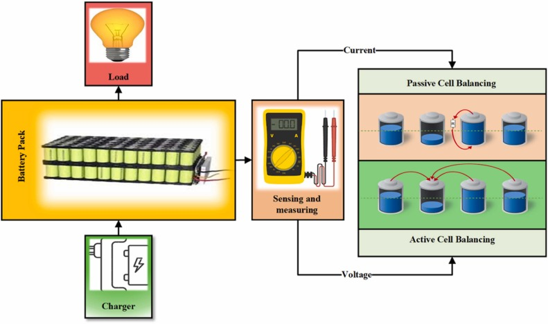
Every lithium battery pack requires a Battery Management System to ensure safe and optimal operation. The BMS functions as the pack's central computer, continuously monitoring cell voltages, pack current, and temperatures while controlling charging and discharging processes. Without proper BMS protection, lithium-ion cells face catastrophic failure risks including thermal runaway, a self-accelerating exothermic reaction that can result in fire or explosion.
Battery Management Systems monitor and control every aspect of pack operation
A BMS capable of monitoring 100 cells with millivolt precision, implementing active balancing, running sophisticated state estimation algorithms, and responding to fault conditions within microseconds requires genuine engineering investment. A BMS that merely prevents the most catastrophic failures while allowing gradual degradation through inadequate balancing or thermal management can be produced for a fraction of the cost. Both packs may carry similar specifications and warranty periods. Their divergent performance emerges only after warranty expiration, and by then the purchasing decision is long past. This information asymmetry shapes the market in ways that do not favor informed consumers.
Voltage monitoring represents the BMS's primary safety function. Individual cells within a pack naturally develop slight capacity variations due to manufacturing tolerances and usage patterns. Without intervention, these differences compound over charge cycles. Some cells reach full charge while others remain partially charged, or conversely, some cells deep discharge while others retain charge. The BMS measures each cell's voltage (typically with ±15mV accuracy) and implements cell balancing to equalize charges across the pack.
Two balancing methods exist: passive and active. Passive balancing dissipates excess energy from higher-charged cells as heat through resistors, slowly bringing all cells to the same voltage level. This simple approach works well for low-power applications but wastes energy. Active balancing transfers energy from higher-charged cells to lower-charged cells using DC-DC converters or capacitors, improving efficiency in larger packs.
The consumer optimizing for purchase price and the consumer optimizing for total cost of ownership make different choices, and the market caters predominantly to the former.
The distinction between passive and active balancing carries implications that extend beyond energy efficiency. Passive balancing operates only during charging, when excess energy can be safely dissipated. Active balancing can operate continuously during charging, discharging, and rest, maintaining cell uniformity that passive systems cannot achieve. Over thousands of cycles, this continuous maintenance dramatically reduces the capacity divergence that ultimately limits pack life. A pack with active balancing might retain 85% capacity after 2,000 cycles; the same cells with passive balancing might reach 70% capacity due to accumulated imbalance. Yet active balancing adds $20-50 to pack cost, an increment that price-sensitive markets reject despite its long-term value. The consumer optimizing for purchase price and the consumer optimizing for total cost of ownership make different choices, and the market caters predominantly to the former.
Current monitoring protects against overcurrent conditions that could damage cells or create hazards. The BMS tracks instantaneous current flow and integrates it over time to calculate state of charge (SoC), the pack's remaining capacity expressed as a percentage. Accurate SoC estimation requires complex algorithms that account for temperature effects, aging, and self-discharge. Advanced BMS implementations also estimate state of health (SoH), predicting remaining useful life based on capacity fade and internal resistance increases observed over time.
Lithium-ion voltage curves remain remarkably flat across the 30-70% SoC range. A cell at 40% charge might show voltage within 50mV of a cell at 60% charge. This flatness defeats simple voltage-based SoC estimation, requiring coulomb counting (integrating current over time) or model-based approaches that account for temperature, rate, and aging effects. Cheap BMS implementations skip this complexity, resulting in SoC displays that diverge from reality by 10-20%. The inaccuracy causes consumer inconvenience but rarely triggers warranty claims, so the economic incentive to improve remains weak.
Temperature management involves multiple sensor points throughout the pack. The BMS monitors individual cell temperatures and ambient conditions, adjusting charging rates or activating thermal management systems when thresholds are exceeded. Lithium-ion cells perform optimally between 20-30°C but can operate from -20°C to 60°C with reduced performance. Charging below 0°C causes metallic lithium plating that permanently damages cells, so the BMS must disable charging or activate pre-warming systems in cold conditions.
BMS Protection Functions
- Overvoltage Protection: Terminates charging if any cell exceeds 4.2V
- Undervoltage Protection: Disconnects load if any cell drops below 2.5V
- Overcurrent Protection: Limits peak current to prevent cell damage
- Over-temperature Protection: Reduces current or shuts down if temps exceed limits
- Short Circuit Protection: Immediately disconnects pack if short detected
- Cell Balancing: Equalizes charge across all cells for uniform aging
Communication interfaces allow the BMS to report pack status to host devices. Consumer electronics typically use I²C or SMBus protocols to transmit voltage, current, temperature, SoC, and SoH data. Electric vehicles employ CAN bus networks that integrate battery data into broader vehicle control systems. Some industrial applications utilize wireless connectivity for remote monitoring of stationary storage installations.
Performance Factors and Longevity
Specifications tell only part of the story when predicting how long a battery pack will last. Depth of discharge significantly impacts cycle life. Shallow discharges (20-80% SoC range) extend battery longevity compared to full 0-100% cycles. Research data from 2024 indicates that limiting discharge to 30-70% SoC can triple cycle life from 800 to 2,400 cycles in consumer-grade lithium-ion cells. This explains why many electric vehicles recommend charging to 80% for daily use, reserving 100% charges for long trips. The advice sounds like unnecessary complication until the battery replacement quote arrives.

Charging practices significantly impact long-term battery health and lifespan
The shallow-discharge longevity benefit stems from electrode stress concentration at extreme states of charge. At 100% SoC, the graphite anode reaches maximum lithium loading. Every available intercalation site is occupied, creating mechanical stress that manifests as particle cracking over repeated cycles. At 0% SoC, the cathode reaches maximum lithium loading with analogous stress effects, compounded by copper current collector dissolution that begins below approximately 2.5V. Operating within the 20-80% window avoids both extremes, dramatically reducing mechanical degradation. The chemistry rewards moderation.
Temperature effects dominate degradation mechanisms. Battery University research demonstrates that storing fully charged lithium-ion cells at elevated temperatures accelerates capacity loss exponentially. A pack stored at 25°C with 40% charge retains 96% of capacity after one year, while the same pack stored at 60°C with 100% charge loses 40% of capacity in the same period. Manufacturers specify optimal storage conditions around 15°C with 40-60% SoC for long-term preservation. Few consumers read these recommendations, and fewer still follow them.
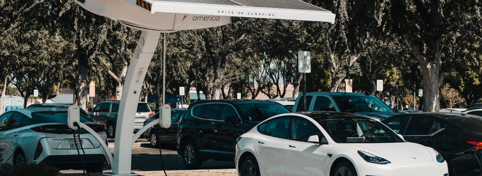
The charging practices that maximize convenience are precisely those that minimize battery lifespan. Leaving devices plugged in continuously, fast charging whenever possible, storing EVs in hot garages: each habit accelerates degradation. A 350kW DC fast charger can add 200 miles of range in 15 minutes, an impressive specification that marketing materials emphasize. The reality that routine fast charging can halve battery lifespan compared to Level 2 charging at 7kW receives less prominent placement. The consumer who fast charges daily may achieve the same cumulative degradation in three years that a Level 2 charger would cause in seven years. The tradeoff between convenience and longevity is real, but the information asymmetry between manufacturers and consumers means the choice is rarely made consciously.
Standard charging at 0.5C-1C (taking 1-2 hours) generates manageable heat and minimizes stress on cell materials. Fast charging at 2C or higher enables convenient 30-minute recharges but accelerates electrode degradation through increased heat generation and mechanical stress from rapid lithium-ion insertion. The 2025 lithium battery market has addressed this trade-off through thermal management improvements and modified cell chemistries that tolerate higher charge rates without proportional degradation. Progress is real, but the fundamental physics has not changed.
Calendar aging occurs even without use. Lithium-ion packs gradually lose capacity simply due to time elapsed since manufacture. Internal chemical reactions slowly consume lithium ions and degrade electrode materials. The solid electrolyte interphase (SEI) layer on the anode, a passivation film that forms during initial charging, continues growing throughout the cell's life. This growth consumes active lithium, increases internal resistance, and eventually reaches a thickness that impedes ion transport. Most consumer lithium battery packs exhibit noticeable capacity loss after 2-3 years regardless of cycle count. Commercial-grade cells used in electric vehicles employ more stable chemistries and sophisticated BMS algorithms to extend calendar life to 8-15 years while maintaining 70-80% of original capacity.
Environmental factors beyond temperature affect performance. Humidity can cause corrosion of external pack components and terminals if water penetration occurs. Vibration and mechanical shock can damage internal connections or cause electrode material delamination in poorly constructed packs. Quality manufacturers implement robust enclosure designs with IP67 ratings (protected against temporary water immersion) and vibration-resistant construction for demanding applications. The price premium for such construction often seems unjustified until a cheaper alternative fails in the field.
The Solid-State Mirage
No discussion of lithium battery technology remains complete without addressing solid-state batteries, the perpetually imminent revolution that has been "five years away" for the past fifteen years. Solid-state designs replace flammable liquid electrolytes with solid ceramic or polymer materials, theoretically enabling higher energy density, improved safety, and longer cycle life. The theoretical advantages are genuine. The engineering challenges have proven more stubborn than optimistic projections suggested, and the gap between laboratory demonstration and volume manufacturing remains vast.

Solid-state battery research continues in laboratories worldwide, though commercial viability remains elusive
The fundamental problem is interfacial. Solid-solid interfaces between electrode and electrolyte develop contact resistance far exceeding liquid-solid interfaces. As cells cycle, the volumetric changes in electrodes create gaps at these interfaces that liquid electrolytes would simply flow around but solid electrolytes cannot accommodate. Current solid-state prototypes demonstrate excellent initial performance that degrades rapidly as interfacial contact deteriorates. Solving this problem requires either electrode materials with minimal volumetric change (sacrificing energy density) or pressure systems that maintain interfacial contact (adding weight and complexity). Neither solution is obviously superior, and both impose costs that erode the theoretical advantages.
Manufacturing presents equally formidable obstacles. Liquid electrolyte filling is a mature, high-throughput process. Solid electrolyte deposition requires vacuum processing or sintering steps that dramatically reduce production speed and increase cost. The most optimistic solid-state cost projections remain 3-5x higher than liquid electrolyte cells at scale, a gap that may narrow but will likely persist for decades. Startups continue to announce breakthroughs and attract investment; production announcements remain conspicuously absent.
Solid-state batteries will eventually achieve commercial viability for specific applications where their safety advantages justify cost premiums: medical implants, aviation, perhaps premium automotive segments where buyers will pay for incremental improvement. The notion that solid-state technology will rapidly displace liquid electrolyte lithium-ion across mainstream applications reflects wishful thinking amplified by investment marketing rather than sober engineering assessment. The liquid electrolyte lithium-ion cell, with all its limitations, will remain the dominant energy storage technology for the foreseeable future. Understanding how battery packs lithium work is not preparing for an obsolete technology. It is understanding the technology that will power the next several decades.
相关主题文章 (See Also):