

What is Battery Pack Assembly?
Battery pack assembly is the manufacturing process of turning cells into usable energy storage systems.
Twenty years ago, this was simple. A few dozen 18650 cells, nickel strips spot-welded in series, a plastic shell on the outside, positive and negative leads brought out, and a laptop battery pack was complete. The entire process could be done on a single table with equipment investment of just tens of thousands of yuan.
Now an electric vehicle battery pack contains several hundred large cells or several thousand small cells, with system voltage of 400 to 800 volts, storing enough energy to power an average household for over a week. Assembling such a battery pack requires a production line covering thousands of square meters, equipment investment of hundreds of millions of yuan, and an engineering team of over a hundred people.
What's the difference between the two? The extreme requirements for consistency, the extreme requirements for safety, and the ability to reliably achieve both in high-volume production.
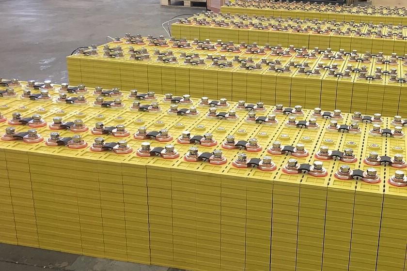
The Incoming State of Cells
Cells coming off the production line at cell factories are not exactly identical.
This isn't a quality control problem. Electrochemical manufacturing processes cannot achieve absolute uniformity. During coating, when slurry is applied to the current collector, there are slight thickness fluctuations. During slitting, electrode dimensions have slight deviations. During electrolyte filling, the amount of electrolyte injected varies slightly. During formation, each cell experiences a slightly different temperature profile. These small differences accumulate, making each cell's capacity, internal resistance, and self-discharge rate slightly different.
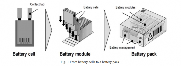
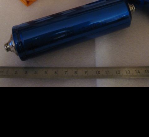
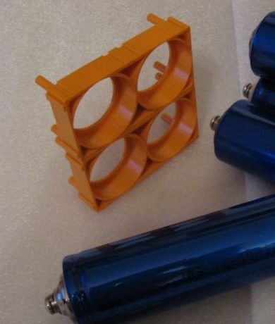
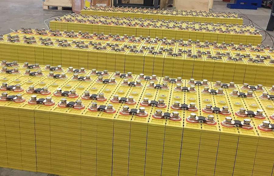
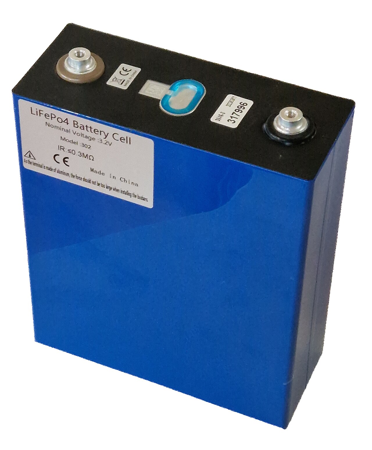
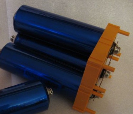
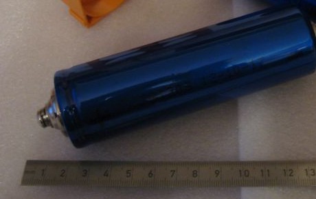
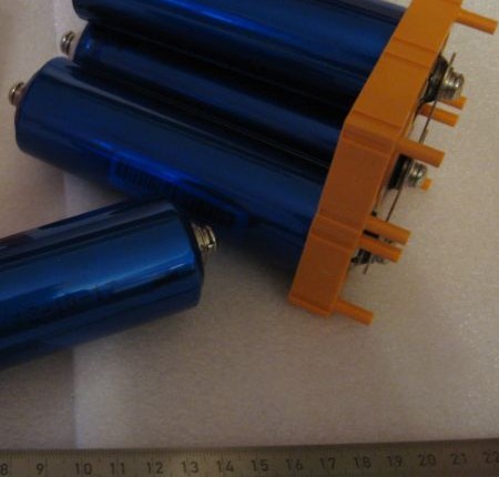
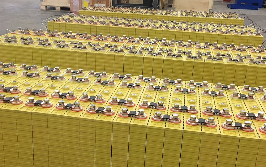
Battery Cells
How large are these differences? Taking a cell with a nominal capacity of 100Ah as an example, capacity might be distributed between 98Ah and 102Ah. Internal resistance might fluctuate by ±5%. Open circuit voltage at the same state of charge might differ by a few millivolts.
These numbers don't look large. Take a single cell and use it alone, and you won't feel any difference at all. Put several hundred cells into one pack, and problems emerge.
When cells are connected in series, the cell with the smallest capacity determines how much energy the entire string can discharge. During charging, the cell with the smallest capacity fills up first, triggering protection cutoff, leaving other cells not fully charged. During discharging, the cell with the smallest capacity empties first, triggering protection cutoff, leaving energy in other cells that can't be discharged. In a 100-series battery pack, if 99 cells have 100Ah capacity and 1 cell has 95Ah capacity, the total usable capacity is 95Ah times 100, not 100Ah times 100.
Internal resistance differences bring another problem. Cells with higher internal resistance generate more heat at the same current. More heat leads to higher temperature, higher temperature accelerates aging, and aging causes internal resistance to increase further. A cell that had internal resistance 5% above average at the factory might become 25% above average after three years. This cell becomes a hot spot in the pack, and the cells around it suffer along with it.
The Logic of Sorting
The way to address incoming material variation is sorting.
Each cell arriving at the pack factory first goes to a testing station. Open circuit voltage is measured, internal resistance is measured, capacity is measured. After testing, cells are grouped based on results, putting cells with similar characteristics together.
Sorting precision requirements have been continuously increasing. Ten years ago, sorting capacity to ±3% was considered acceptable. Five years ago it tightened to ±2%. Now supplying to leading automakers requires ±1%. Internal resistance sorting has tightened from ±5% to ±3% to ±2%. Open circuit voltage has tightened from ±5mV to ±3mV to ±2mV.
The driving force for tightening comes from accumulated production data. After cars have been running for several years and come back for inspection, batches that were sorted loosely at the beginning show noticeably faster degradation. As statistical sample sizes increase, correlations become clear: there is a predictable amplification relationship between initial differences and end-of-life differences. A 1% initial difference might become 5% at end of life. A 3% initial difference might become 15% at end of life.
Sorting equipment precision requirements have risen accordingly. Voltage measurement needs to reach ±0.1mV level, internal resistance measurement needs to reach ±0.1mΩ level. Testing environment temperature needs to be controlled to 25±1°C, because internal resistance is temperature-sensitive, and a 2°C temperature deviation might introduce 1% measurement error.
Some pack factories choose to make their own cells, partly because of sorting. Purchasing external cells means accepting the incoming consistency of cell suppliers, with quality depending on the supplier's quality control capability and willingness to cooperate. Making your own cells, if consistency isn't good enough, you can trace backwards to find whether it's a coating problem, electrolyte filling problem, or formation problem, and make targeted improvements.
Sorting produces rejected items. Cells that don't meet grouping standards can't be used in this batch of packs; they either get downgraded to products with lower requirements, or wait for the next batch of cells with matching characteristics to form a group. The stricter the sorting, the higher the rejection rate, the higher the cost. There's a balance point to find here.
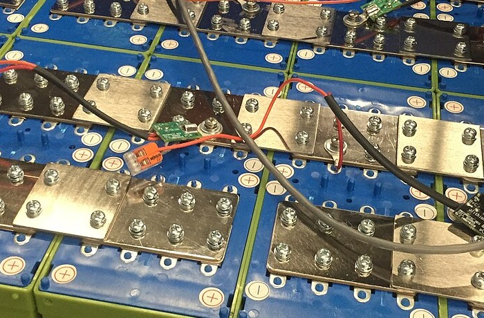
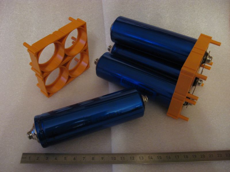
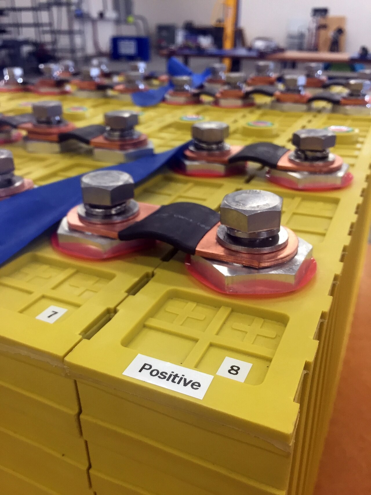
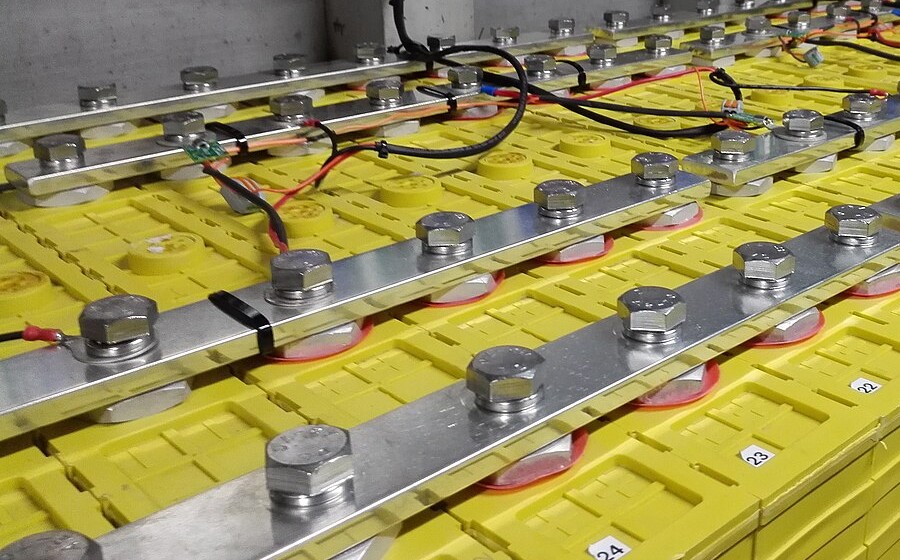
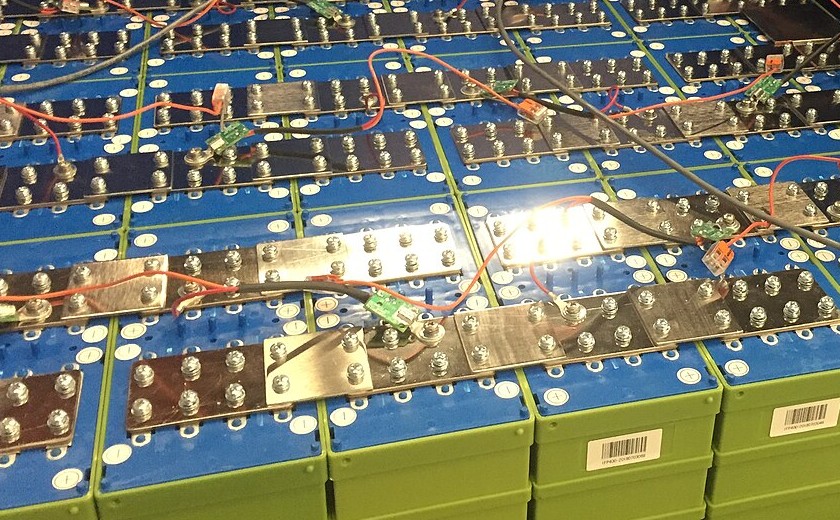
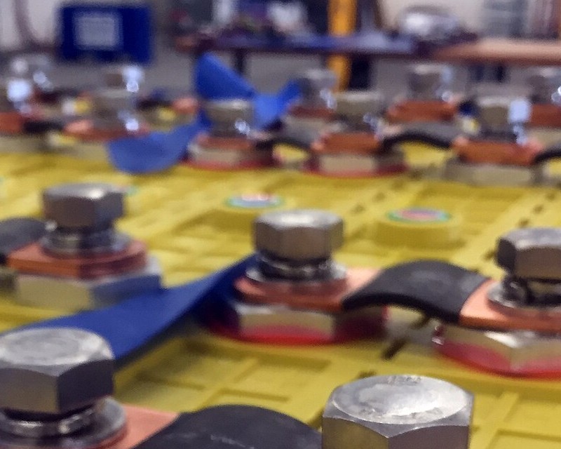
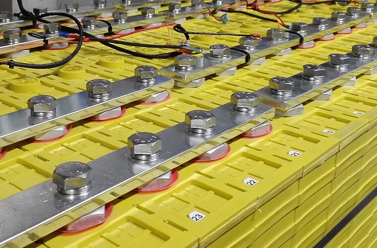
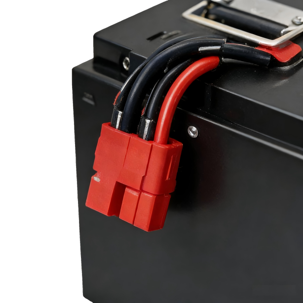
Connecting the Cells
Sorted cells need to be assembled into circuits. Series connection increases voltage, parallel connection increases capacity. A 400V battery pack needs about 100 cells in series. If each series node has several cells in parallel, capacity is multiplied by the parallel count.
The connections between cells carry large currents; several hundred amperes is a common level. Every 0.1 milliohm increase in connection resistance produces 1 watt of additional heat at 100 amperes. This 1 watt of heat is concentrated on a very small contact surface, causing temperature to rise significantly. High temperature accelerates oxidation of the contact surface, the oxide layer has higher resistance, generating more heat, creating a vicious cycle. After several years, a connection point that wasn't done well initially might become the hottest spot in the entire pack.
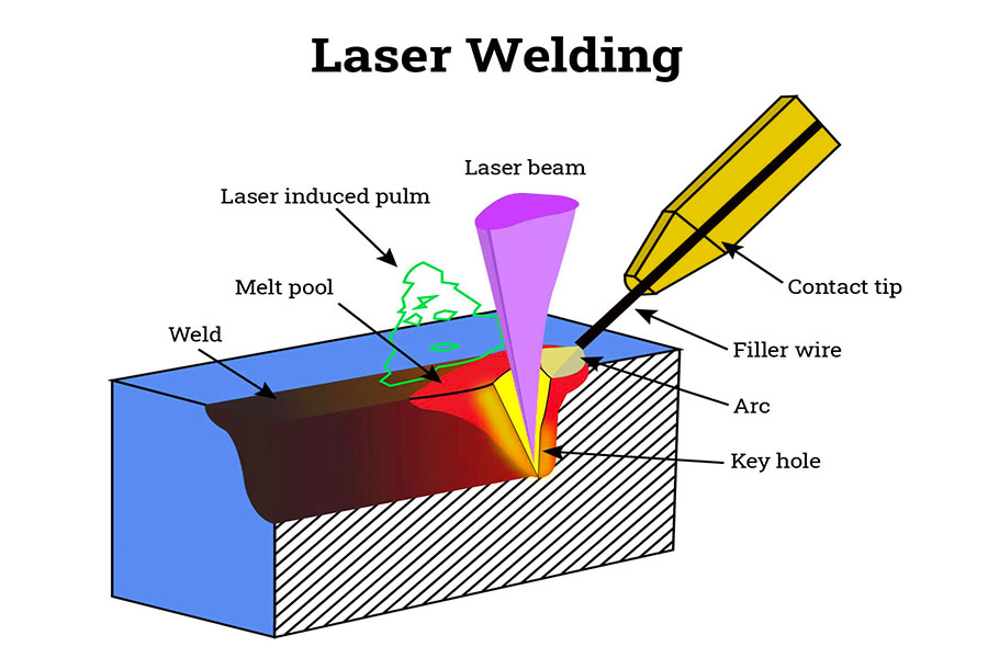
Laser Welding
Laser welding is currently the mainstream connection method. A several-kilowatt laser beam is focused to a spot of a few tenths of a millimeter, instantly melting the metal to form a weld seam. The advantage of laser welding is the small heat-affected zone; only a very narrow region near the weld seam is heated, and adjacent cells and other components are unaffected. Welding speed is fast; a single weld point can be completed in a fraction of a second. Weld seam quality is stable; once parameters are tuned, consistency is very high.
Laser welding equipment is expensive. A single welding workstation costs several million yuan, and adding supporting positioning fixtures, vision systems, and shielding gas systems, a welding production line investment exceeds ten million yuan. Equipment is expensive, but considering the impact of welding quality on pack lifespan and safety, this money cannot be saved.
Ultrasonic welding solves a type of problem that laser welding doesn't handle well. The electrodes inside cells are very thin metal foils; aluminum foil is around ten micrometers, copper foil is several micrometers. These thin foils need to be gathered onto tabs to conduct current out. The gathering method is to stack dozens or even hundreds of layers of foil together and weld them to the tab. Laser welding has problems with this; slightly too much energy burns through the thin foils, slightly too little energy doesn't weld through. Ultrasonic welding uses a different principle, using high-frequency vibration to create friction heating between metal surfaces to form a connection, without melting the base material, which is particularly friendly to thin foils.
Resistance welding is still in use, mainly for cylindrical cell packs. Nickel strips span across two cell tops, spot welder electrodes press down, pass large current, and resistance heating welds the nickel strip to the cell terminals. Equipment is cheap, operation is simple, speed is fast. Welding quality isn't as stable as laser welding, but cylindrical cell packs usually have redundant designs; two nickel strips are welded to each cell top, the cell is only lost if both strips break, so single weld quality requirements are reduced.
Welding quality inspection is a headache. A weld point might look fine from the outside but have cold joints, porosity, or cracks inside. Destructive inspection can reveal these; cut open the weld point and do metallographic analysis, and no problem can hide, but that weld point is scrapped. For non-destructive inspection, X-ray can see internal structure, ultrasound can detect defects, infrared thermal imaging can find points with abnormal resistance. These methods are all useful and all have limitations; some defects can be detected, some cannot. In high-volume production, it's impossible to do full non-destructive testing on every weld point; the time cost and economic cost are unbearable. The common practice is to strictly control welding parameters, use statistical process control to monitor parameter variation, and assume that when parameters are in control, welding quality is also in control. This assumption holds most of the time, occasionally it doesn't, and some defects slip through.
Physical Constraints of Thermal Management
Lithium batteries generate heat during charging and discharging; this is an inherent characteristic of electrochemical processes. The larger the current, the more heat generated. If heat isn't removed in time, cell temperature will rise.
Lithium batteries prefer to operate between 20°C and 45°C. Below this range, electrolyte viscosity increases, ion migration slows, internal resistance rises, and available power decreases. Above this range, side reactions accelerate, SEI film continues to grow consuming lithium ions, and capacity degradation accelerates. Temperature differences between cells also need to be controlled, usually required to be within 5°C; otherwise cells at higher temperatures age faster, and after several years pack consistency will deteriorate significantly.
Early battery packs used air cooling. Fans blew air across cell surfaces, and air carried heat away to outside the pack. Air cooling systems are simple, low cost, reliable, with no concerns about liquid leakage.
The problem with air cooling is limited heat exchange capability. Air's thermal conductivity is two orders of magnitude lower than liquid; even increasing airflow doesn't improve heat exchange capability much. For low-power, slow charge and discharge applications, air cooling can cope. For high-power, fast charge and discharge applications, air cooling can't remove that much heat, and cell temperature will exceed limits. Current electric vehicles pursue fast charging, charging to 80% in twenty minutes; the heat generated during this process cannot be blown away by air.
Liquid cooling has become the mainstream solution. Coolant flows through pipes, passes through cold plates attached to cells, carries heat away, then flows to a radiator to release heat to the environment. Liquid has much stronger heat exchange capability than air; at the same temperature difference, it can carry away much more heat.
Liquid cooling systems add quite a few components. Cold plates are needed, covering all cells that need cooling. Pipes are needed, connecting cold plates to external radiators. A pump is needed to drive coolant circulation. An expansion tank is needed to accommodate coolant volume changes from thermal expansion and contraction. Control valves are needed to regulate coolant flow. These components add up to significant weight, considerable cost, and introduce new failure modes.
The pump can fail. Seals can leak. Pipes can clog. Coolant performance degrades with use. These problems all exist in traditional automotive engine cooling systems; they're not new, and there are mature countermeasures. Battery pack liquid cooling has a special risk: coolant leaking into the battery pack. Inside the battery pack is several hundred volts of high voltage, and most coolants contain ethylene glycol, which has some conductivity. Leakage could cause short circuits, and short circuits could cause thermal runaway. This risk requires sealing to be extremely reliable, along with leak detection methods.
There is an interface between the cold plate and cells. The thermal resistance of this interface greatly affects the effectiveness of the entire cooling system. Cell surfaces are not flat; they have curvature, burrs, and tolerances. Cold plate surfaces are also not absolutely flat. When two non-flat surfaces are placed together, there will be gaps. The gaps contain air, and air has extremely low thermal conductivity, so heat cannot pass through.
The solution is to fill in thermal interface materials. Thermal pads or thermal adhesive fill between cells and cold plates, pushing out the air in the gaps. Thermal interface materials have thermal conductivity two orders of magnitude higher than air, allowing heat to transfer smoothly to the cold plate.
How thick should the thermal interface material be? Too thin and coverage is incomplete, with air remaining in some places. Too thick and thermal resistance increases, actually reducing thermal efficiency. It's usually controlled to a range of a few tenths of a millimeter to one or two millimeters. Every cell position must be filled, and thickness must be uniform; this places high demands on dispensing equipment and process control. With several hundred cells, if the thermal interface at every position is done well, pack thermal uniformity can be guaranteed. If problems occur at this step, some cells have good heat dissipation and some have poor heat dissipation, and temperature difference control will exceed limits.
Some high-end models have started using direct cooling systems. Instead of liquid coolant, the air conditioning system's refrigerant evaporates directly in pipes inside the battery pack to absorb heat. Refrigerant evaporation is a phase change process, with heat absorption capability stronger than liquid cooling at the same temperature difference. System complexity increases, cost increases, but in exchange for stronger thermal management capability, with applications in models pursuing ultimate performance.
What BMS Does
BMS stands for Battery Management System.
The functions are straightforward to state: monitor battery status, protect battery safety, communicate with external systems. Elaborated further, there's a lot involved.
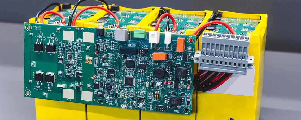
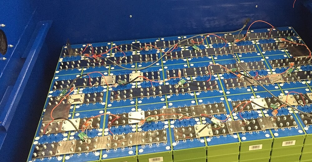
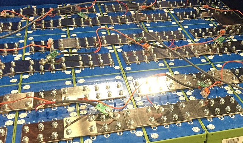
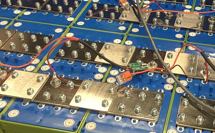
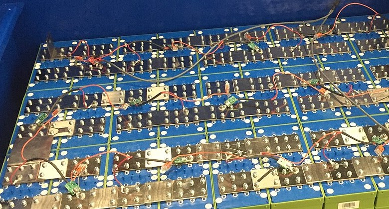
BMS Circuit
Monitoring needs to cover every parameter that needs attention. Voltage of each series unit must be measured individually, used to judge whether there's overcharge or over-discharge, used to estimate remaining capacity. Current of the entire pack must be measured, used to calculate power, used to estimate capacity changes. Temperature sensors must be placed at least at several key locations; some packs have a sensor at each module or even every few cells. Insulation resistance between high-voltage circuits and the vehicle body must be monitored; declining insulation is a danger signal.
Measurement itself isn't difficult; what's difficult is measuring accurately. Voltage measurement needs millivolt-level precision, because the correspondence between cell voltage and remaining capacity is very flat in some regions, and a few millivolts difference might correspond to several percentage points difference in remaining capacity. Current measurement needs ampere-level or even sub-ampere-level precision, because remaining capacity estimation relies on current integration, and current measurement bias accumulates over time. Temperature measurement needs precision within 1°C, because many protection thresholds are temperature-related, and inaccurate temperature measurement causes protection to trigger falsely or fail to trigger when it should.
Protection functions are implemented based on monitoring. When voltage exceeds the upper limit, charging must be cut off to prevent overcharge. When voltage falls below the lower limit, discharging must be cut off to prevent over-discharge. When temperature exceeds the upper limit, power must be limited or the circuit must be cut off to prevent overheating. When current exceeds the upper limit, power must be limited or the circuit must be cut off to prevent overcurrent. When insulation resistance falls below the lower limit, an alarm must sound or high voltage must be cut off to prevent leakage.
How are these protection thresholds set? It's not as simple as a fixed number. Charging upper limit voltage is related to temperature; at low temperatures the upper limit must be lowered to prevent lithium plating. Discharge lower limit voltage is related to current; during high-current discharge, voltage is pulled down by internal resistance, and this factor must be deducted. Temperature upper limit is related to duration; brief over-temperature might be acceptable, sustained over-temperature definitely isn't. These complex relationships must be reflected in BMS algorithms; it's not simple threshold comparison.
Remaining capacity estimation is one of the most technically demanding parts of BMS. Users want to know how many more kilometers they can drive; behind this question is: how much usable energy remains in the battery pack.
The simple approach is the lookup table method. Measure battery voltage, look up a table of voltage versus remaining capacity correspondence, read out remaining capacity. The problem with this approach is that the relationship between voltage and remaining capacity is not fixed. Just after charging versus after resting for several hours, at the same remaining capacity, voltage is different. When temperature changes, the correspondence also changes. When aging occurs, the correspondence changes again. Using the lookup table method for estimation, error might be 10% or even more.
A more accurate approach is ampere-hour integration. Record how much charge went in, record how much charge came out, calculate the difference. The problem with this approach is that current measurement has bias, and bias accumulates. After running for one day, accumulated bias might be 1%; after running for one week, accumulated bias might be 5%. There's also self-discharge; during rest, the battery slowly loses capacity, and without charging or discharging, integration alone cannot detect self-discharge.
An even more accurate approach is the model method. Run a mathematical model of the battery in the BMS, predict what voltage should be based on input current, compare the predicted value with the measured value, and if there's deviation, correct the state variables in the model. There are many variants of this type of algorithm: Kalman filter, extended Kalman filter, unscented Kalman filter, particle filter. The names are different but the principles are similar; all use the approach of model prediction plus measurement correction. When the model method is done well, estimation accuracy can reach within ±3%, much better than lookup table and pure integration methods.
Balancing is another function of BMS. No matter how well sorting is done, cells will gradually differentiate during use; some have faster capacity degradation, some slower. Without intervention, the cell with the lowest capacity determines the pack's usable capacity, and the surplus in other cells is wasted.
Passive balancing works by finding cells with high voltage and discharging the excess energy through resistors, turning it into heat. This approach is simple, circuit cost is low; the disadvantage is that energy is wasted.
Active balancing works by transferring energy from cells with high voltage to cells with low voltage. This approach doesn't waste energy; the disadvantage is that the circuit is complex and costly. DC-DC converters are needed to move energy between cells; the transfer itself has losses, with efficiency around 85% to 95%.
Currently most production BMS use passive balancing. Balancing current is usually at the level of tens to hundreds of milliamperes, not large, mainly used to compensate for voltage divergence caused by self-discharge differences. High-current active balancing has some results in the research stage, but production applications are still few.
Differences between BMS hardware are not visible from the outside, but capability gaps can be very large. A BMS chip set might sell for twenty to thirty US dollars, but the algorithm development, calibration testing, and failure mode analysis behind it might have cost tens of millions of dollars. Two BMS systems with similar procurement costs might differ by an entire tier in performance.
Structure and Sealing
A battery pack needs a housing to contain the cells and other components.
The housing's function is not just containment, but also protection, sealing, mounting, and participating in overall vehicle structure. These functions superimposed together create very high requirements for housing design and manufacturing.
The protection function requires the housing to withstand external impacts. During vehicle driving, the bottom might be hit by stones or scrape against road protrusions from bottoming out. Battery packs are usually placed at the bottom of the vehicle, directly exposed to these risks. The thickness and material of the bottom tray must be able to withstand these impacts; a single stone shouldn't be able to puncture the battery pack. In collision accidents, the housing also needs to absorb some energy, reducing the impact transmitted to the cells.
The sealing function requires the housing to be waterproof and dustproof. Cars need to drive in rain, need to cross water-logged sections; battery packs cannot let water in. If water gets in, in an environment of several hundred volts high voltage, short circuits will occur, with serious consequences. The industry-standard protection rating requirement is IP67, meaning complete prevention of dust entry and no water entry after 30 minutes of immersion in water 1 meter deep. Some automakers require higher, achieving IP68.
To achieve IP67 or IP68, the joint between the housing upper cover and tray is the focus. This seam must be sealed with sealant or gaskets; if not sealed tightly, it will leak. The seal must withstand thermal expansion and contraction from temperature changes, must withstand vibration and twisting from vehicle driving, and must maintain sealing performance throughout the vehicle's service life. Locations where cables pass through the housing are also sealing challenges: high-voltage wiring harnesses, low-voltage signal wires, coolant pipes; each wall penetration location must be individually sealed.
The mounting function requires the housing to provide interfaces for connection to the vehicle body. The battery pack must be fixed to the vehicle body; mounting points must be able to bear the entire pack's weight and also withstand inertial forces from vehicle acceleration, deceleration, and turning. Fastening methods include bolt connections and clip connections; bolt connections have high strength and are convenient to disassemble and reassemble, clip connections are fast and suitable for automated production lines. The layout of mounting points must consider stress distribution; it's not acceptable for a few points to bear most of the load while other points bear almost none.
In material selection, aluminum alloy has become mainstream. Aluminum's density is one-third that of steel; at the same strength, weight is much lighter. Electric vehicles are sensitive to weight; lighter means more cells can be installed or range can be increased; aluminum alloy is worth using even though it's more expensive. Manufacturing methods for aluminum alloy housings include casting, extrusion, and stamping. Casting is suitable for large parts with complex shapes, such as integrated trays. Extrusion is suitable for long pieces with fixed cross-sections, such as frames. Stamping is suitable for sheet metal parts, such as upper covers.
CTP (Cell to Pack) structure eliminates the module layer; cells are installed directly into the pack housing. Traditional structure has cells first assembled into modules, modules have their own housings and wiring harnesses, then modules are installed into the pack. CTP eliminates module housings and module-level wiring harnesses, improving space utilization, reducing weight, and reducing assembly steps. BYD's blade battery packs and CATL's Qilin battery packs both use CTP structure.
CTC (Cell to Chassis) structure goes even further. The battery pack is no longer an independent assembly mounted to the vehicle body; instead, the battery pack and vehicle body are integrated as one. The pack's upper cover becomes the vehicle's floor, the pack's frame becomes part of the vehicle body structure. Tesla's Model Y produced at US factories uses this structure; the rear body is a large aluminum casting, cells are installed in cavities of the casting, with foam material poured in between to fill gaps.
CTC eliminates the two redundant layers of battery pack upper cover and vehicle body floor in traditional structure, with significant weight reduction effect. At the same time, vehicle body rigidity improves because the battery pack participates in structural load-bearing. The trade-off is that repair becomes difficult. Battery packs with traditional structure can be removed as a whole from under the vehicle for servicing; CTC structure batteries are part of the vehicle body, cannot be removed as a whole, and problems can only be addressed while on the vehicle. Accident damage that could previously be resolved by replacing modules might now require replacing the entire rear body.
Testing and End-of-Line
Completed battery packs must be tested before they can leave the factory.
EOL Testing
Insulation testing checks the insulation performance between high-voltage circuits and the pack housing. Test equipment applies voltage between high-voltage terminals and the housing, measures leakage current, and calculates insulation resistance. Insulation resistance that is too low indicates leakage risk and cannot leave the factory. Industry standards typically require insulation resistance no less than 100Ω/V; a 400V battery pack must have insulation resistance no less than 40kΩ. Some automakers have stricter internal standards, requiring 500Ω/V or even higher.
Dielectric withstand testing checks whether insulation will break down under high voltage impact. Test equipment applies voltage much higher than normal operating voltage between high-voltage terminals and the housing, maintains it for a period of time, and observes whether the insulation layer will be punctured. Typical test voltage is twice the operating voltage plus one thousand volts; a 400V battery pack is tested at 1800V. Duration is usually one minute. Dielectric withstand testing is much more stringent than insulation testing; battery packs that pass dielectric withstand testing have sufficient insulation margin.
Air tightness testing checks the sealing performance of the pack housing. The test method is to pressurize the pack with gas, maintain for a period of time, and observe how much pressure drops. Rapid pressure drop indicates there's a leak somewhere; sealing is unqualified. Test pressure is typically around ten kPa, hold time is from several minutes to over ten minutes. This test can detect problems like improperly pressed seals, unevenly applied sealant, and pinholes or cracks in the housing.
BMS functional testing checks whether all management system functions are normal. Is voltage measurement accurate? Every measurement channel must be tested and compared against standard voltage sources. Is temperature measurement accurate? Sensors are placed in known temperature environments to test. Is current measurement accurate? Known currents are passed through to test. Are protection functions responsive? Conditions of overvoltage, undervoltage, over-temperature, and overcurrent are artificially created to see if protection triggers. Is communication normal? Standard messages are sent to see if responses are correct. Is the balancing function working? Voltage inconsistency is created to see if it can balance back.
Charge and discharge testing checks the battery pack's capacity and power capability. Full charge then full discharge to measure capacity, comparing against nominal value. Maximum discharge power and maximum charge power are measured under specified conditions to see if design specifications can be met. This test takes the longest; a complete charge-discharge cycle takes several hours. Sometimes to meet production capacity, the test process is simplified to test only a partial state of charge range.
Battery packs that pass all tests can be labeled as qualified and leave the line. Test data is archived and bound to the battery pack's identification number for traceability.
Some Current Industry Structure Conditions
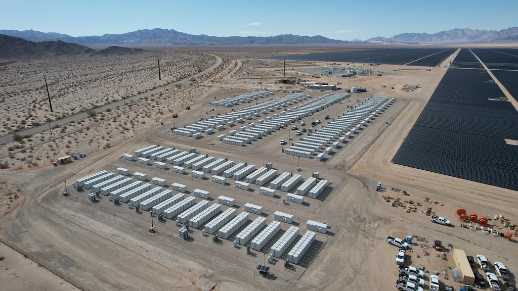
Battery pack assembly capacity is highly concentrated in East Asia. China accounts for the majority of global capacity, with Korea and Japan having a portion. Europe and North America are building capacity but haven't reached scale yet.
CATL and BYD together account for over fifty percent of global electric vehicle battery installation volume. Both companies use a vertically integrated model, making both cells and packs. Cells are produced and then assembled into battery packs at their own pack factories to supply automakers, without going through third parties.
There are also companies that specialize in making packs without making cells. They purchase cells from cell factories, complete pack assembly themselves, and sell to automakers. The advantage of this model is flexibility; they can choose cells from different suppliers according to customer needs and can customize different pack solutions for different vehicle models. The disadvantage is weak control over incoming material consistency, and procurement prices can't match the self-supply prices of large manufacturers.
Automaker choices are also diverging. Some automakers purchase externally entirely, buying finished battery packs from CATL, LG, or other suppliers, and just install them in vehicles. Some automakers build their own pack factories, buying cells and assembling them themselves, keeping the pack process in their own hands. Some automakers go even further upstream, building their own cell factories for complete vertical integration.
Tesla's approach has evolved. Early on, they relied entirely on Panasonic to supply cells and did the pack themselves. Later they introduced LG and CATL as cell suppliers, diversifying supply sources. Then they developed their own 4680 cells, producing them at US factories. Although production ramp-up has been slower than expected, the direction is toward self-supply.
BYD has made its own cells and packs from the beginning. After launching the blade battery, the entire power battery industry re-examined the lithium iron phosphate route, and BYD's accumulated experience on this route became a competitive advantage.
European automakers collectively felt anxious for several years. Realizing that batteries are the highest value component of electric vehicles, continuing to purchase externally means giving away profits. They collectively invested in building factories; Northvolt was the most watched among them, received a lot of money, built factories, struggled greatly with production ramp-up, and filed for bankruptcy reorganization at the end of 2024. The construction progress of Europe's local battery industry has been much slower than expected, and in the short term they still have to rely on Asian suppliers.
The situation in North America is heavily influenced by policy. The Inflation Reduction Act provides subsidies for batteries produced locally, calculated at tens of dollars per kWh, a considerable amount. Korean battery manufacturers are very enthusiastic about building factories in North America, with several joint venture projects with American automakers. Chinese battery manufacturers face barriers to building factories directly in North America due to geopolitical factors, entering through detours via Mexico or through technology licensing arrangements.
相关主题文章 (See Also):