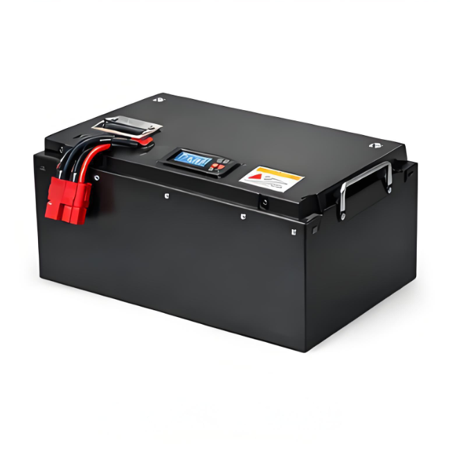


The global shift toward lithium-based 12V batteries has been swift and largely unexamined. Millions of units now power RVs, boats, solar installations, and backup systems, yet most users treat these devices as black boxes. Batteries fail prematurely, capacity disappoints, and warranties go unclaimed because users cannot distinguish manufacturing defects from self-inflicted damage.
Electrochemical Foundations
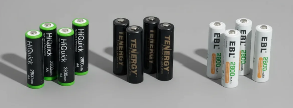
Why Four Cells and Not Three or Five
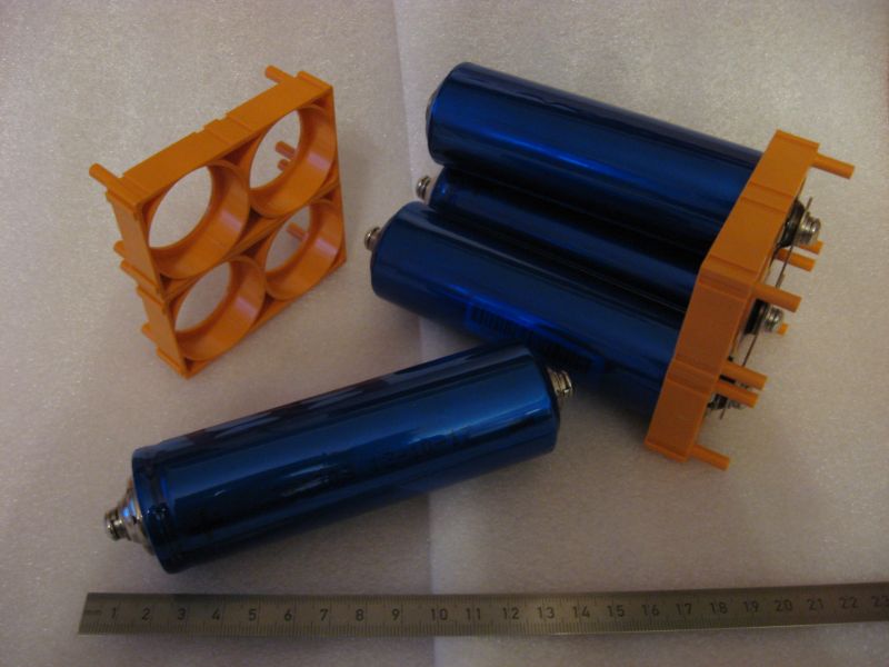
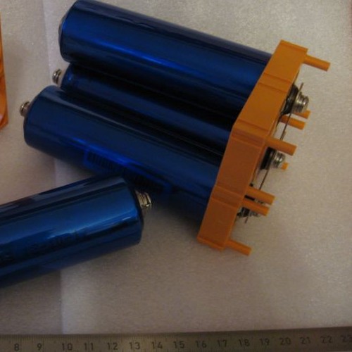
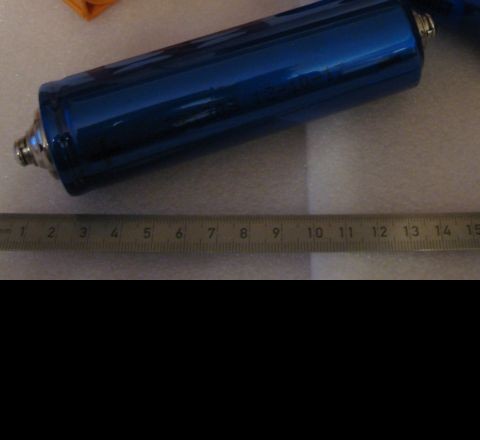
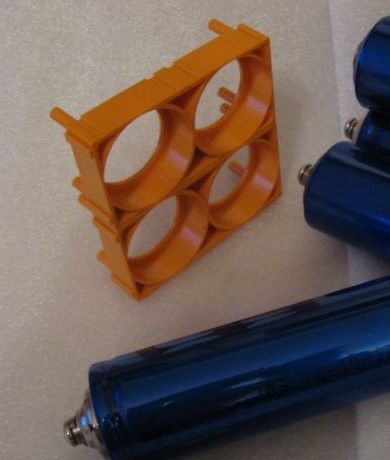
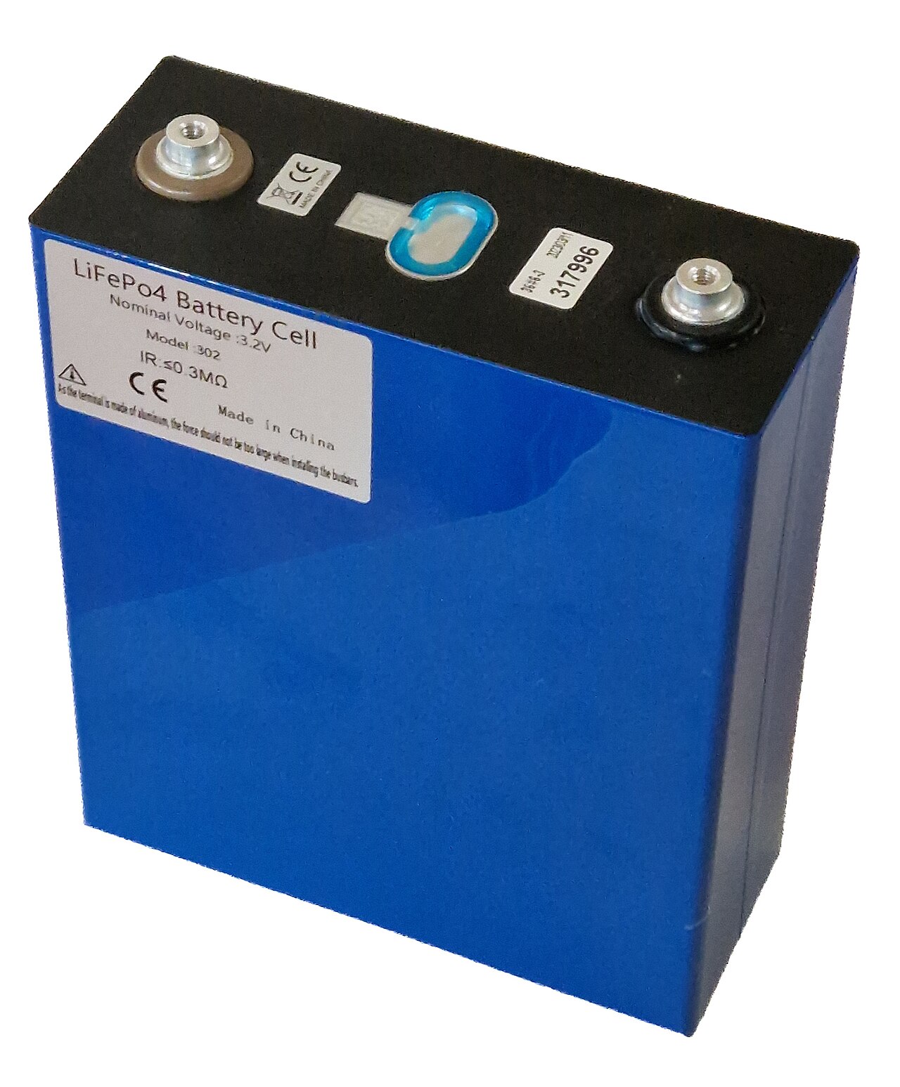
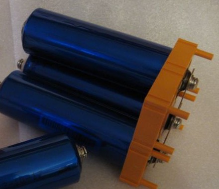
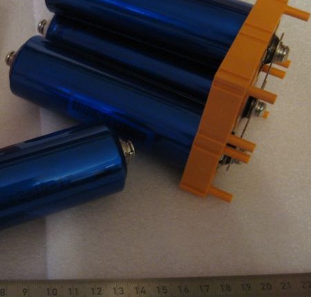
A 12V lithium battery achieves its nominal voltage through four cells connected in series. Each lithium iron phosphate cell operates at 3.2V nominal, yielding 12.8V combined. Three cells would deliver only 9.6V. Five cells would hit 16V, exceeding voltage tolerances of equipment designed for traditional batteries.
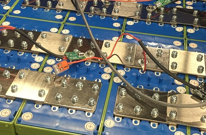
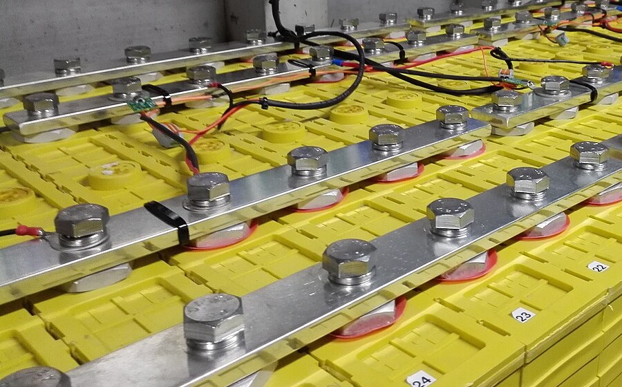
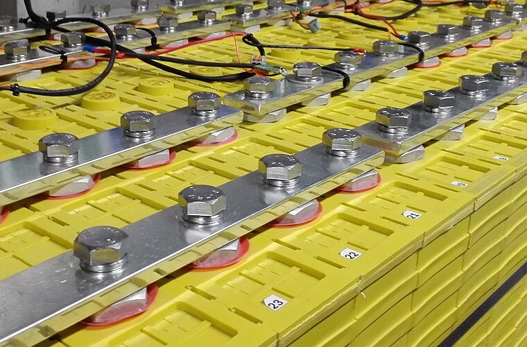
Series architecture creates a vulnerability that shapes every aspect of battery management. The weakest cell limits the entire pack. A single cell reaching discharge cutoff voltage forces the entire battery to stop delivering power, regardless of energy remaining in other cells. A single cell reaching charge voltage limit terminates charging for the pack. Cell matching and balancing consume enormous engineering attention in quality battery systems for exactly this reason.
Four cells also establish the thermal management challenge. Heat generated in any cell conducts to neighbors, creating thermal coupling that can cascade into pack-level problems.
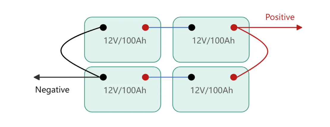
Battery cells arranged in series configuration for optimal voltage output
Lithium: Why Nothing Else Works
Lithium occupies its position in battery chemistry through physics that competing elements cannot replicate. Atomic number 3. Lowest atomic mass of any metal. Standard electrode potential of negative 3.04V versus the standard hydrogen electrode, exceeding any other metal and providing the thermodynamic basis for high cell voltage.
Carrying a single positive charge with ionic radius of 0.76 angstroms, lithium ions insert into crystal structures that reject larger ions. High charge-to-size ratio gives lithium ions exceptional mobility through both solid electrode materials and liquid electrolytes.
Sodium-ion batteries have attracted research attention for stationary applications where weight matters less, but sodium's larger ionic radius reduces energy density by roughly a third while offering minimal cost advantage at current lithium prices. Magnesium and aluminum batteries remain laboratory curiosities despite decades of research.
Cathode Chemistry
For 12V applications, lithium iron phosphate commands roughly 90% market share. Cathode choice determines almost everything about how a battery behaves, fails, and ages, which justifies extended examination.
LiFePO4 crystallizes in the olivine structure. Iron atoms occupy octahedral sites coordinated by six oxygen atoms. Phosphate groups provide structural reinforcement through strong covalent phosphorus-oxygen bonds. Lithium ions reside in channels running parallel to the crystallographic b-axis, these channels providing the pathways for lithium insertion and extraction during cycling.
One-dimensional lithium transport in olivine structures creates both the primary limitation and the primary safety advantage of LiFePO4.
Channels constrain lithium movement to a single direction, reducing ionic conductivity compared to layered structures where lithium can move in two dimensions. Reduced conductivity limits rate capability. But the same structural constraints prevent the oxygen release that makes cobalt-based cathodes dangerous.
When lithium cobalt oxide loses lithium during charging, cobalt ions occupy unstable high oxidation states. Above around 150°C, the structure releases oxygen, which reacts exothermically with electrolyte in a self-accelerating thermal runaway. LiFePO4 contains oxygen bound tightly in phosphate groups that do not release even at temperatures exceeding 270°C. Iron's redox couple maintains stability without oxygen participation, eliminating the thermal runaway pathway responsible for lithium battery fires in consumer electronics and electric vehicles.
LiFePO4 cells tolerate abuse that would destroy other chemistries. Overcharge them moderately and they degrade gracefully rather than venting or catching fire. Overdischarge them and copper dissolution damages the anode, but the cathode survives. Subject them to mechanical damage and they typically fail open rather than shorting catastrophically. This abuse tolerance explains why LiFePO4 dominates applications where batteries operate without sophisticated thermal management or where untrained users interact with the system directly.
LiFePO4's voltage plateau at 3.2-3.3V sits lower than cobalt at 3.7V or nickel at 3.6V, directly reducing energy density. Engineering cannot change this within the chemistry. Accepting lower energy density in exchange for dramatically improved safety and cycle life makes overwhelming sense for 12V applications where the battery occupies fixed installation space rather than being carried.
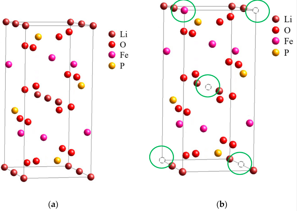
The crystalline structure of lithium iron phosphate enables exceptional stability and longevity
A phenomenon that rarely appears in manufacturer literature but matters enormously in practice: LiFePO4 capacity varies significantly with discharge rate in ways that differ from other chemistries. The one-dimensional lithium transport channels create bottlenecks at high currents. A cell rated at 100Ah when discharged over 20 hours may deliver only 85Ah when discharged in one hour. Other lithium chemistries show this effect too, but LiFePO4's channel-limited transport exaggerates it. Users who size systems based on nameplate capacity and then draw high currents discover their actual capacity falls short.
Another observation from field failures: LiFePO4 cells from different manufacturers, even when using nominally identical chemistry, show dramatically different cold-weather performance. Some cells deliver 70% of rated capacity at minus 10°C. Others from budget suppliers deliver barely 40% at the same temperature. The difference lies in electrode porosity, electrolyte formulation, and particle size distribution, none of which appear on specification sheets. Testing a sample cell at low temperature before committing to a large purchase has prevented many expensive disappointments.
Graphite Anodes
Graphite appears unremarkable. Apparent simplicity conceals a remarkable electrochemical host.
Graphene sheets stack with 3.35 angstrom spacing. Each layer comprises carbon atoms in hexagonal arrangement. Weak van der Waals forces between sheets permit layer sliding and allow foreign atoms to insert between layers without breaking the carbon framework.
Lithium intercalation into graphite proceeds through staging phenomena. At low lithium content, lithium ions insert into every fourth interlayer gallery, creating Stage 4 structure. As lithium content increases, staging transitions through Stage 3, Stage 2, and finally Stage 1 where lithium layers occupy every interlayer space.
Staging allows graphite to accept lithium at reasonable rates despite ions needing to penetrate deep into particle interiors. Lithium does not uniformly fill graphite from surface to center. Stage boundaries propagate through the particle instead, with fully lithiated Stage 1 regions growing at the expense of less lithiated stages. Boundary propagation requires diffusion only across the narrow boundary region rather than through the entire particle thickness.
Maximum lithium content corresponds to one lithium per six carbon atoms, the LiC6 stoichiometry. Fundamental limit of the crystal structure. Has not changed since graphite anodes entered commercial production in 1991.
Silicon Anode Research
Silicon anodes promise far higher capacity through alloying rather than intercalation. Silicon expands by 300% as lithium inserts, then contracts equally during discharge. Volumetric cycling fractures pure silicon electrodes within tens of cycles, destroying the conductive network connecting active material to current collectors. Current commercial silicon implementations limit silicon content to 5-15% in composite anodes, blending silicon particles with graphite and specialized binders. These composites achieve modest capacity improvement while maintaining adequate cycle life. Claims of silicon anode breakthroughs deserve skepticism. Volume expansion has resisted solution for over two decades despite enormous research investment.
Electrolyte
Electrolyte receives less attention than electrodes in popular discussions of battery technology, yet electrolyte properties often limit practical battery performance more severely than electrode characteristics.
The requirements form an impossible specification: conduct lithium ions rapidly, resist electronic conduction absolutely, remain stable against both highly reducing anodes and highly oxidizing cathodes, function across wide temperature ranges, avoid reactions that consume lithium inventory or generate dangerous products.
Commercial 12V lithium batteries employ lithium hexafluorophosphate dissolved in mixed organic carbonates. LiPF6 provides high ionic conductivity and adequate stability, though thermal decomposition above 60°C and sensitivity to trace moisture create ongoing management challenges.
Electrolyte formulation remains one of the most challenging aspects of battery engineering
Ethylene carbonate appears in virtually all lithium battery electrolytes because it forms stable solid electrolyte interphase films on graphite anodes. SEI layers emerge during initial battery cycling as electrolyte components decompose at the low potentials experienced by charged graphite anodes. Decomposition would be catastrophic if it continued indefinitely. EC-based electrolytes solve this by forming a passivating layer that permits lithium ion transport while blocking further electrolyte access to the reactive graphite surface.
SEI composition includes lithium carbonate, lithium fluoride, lithium oxide, and various organic species derived from electrolyte decomposition. Formation consumes a significant fraction of initial lithium inventory during first charging. Irreversible loss. SEI continues growing slowly throughout battery life, gradually consuming additional lithium and increasing cell impedance.
Temperature affects electrolyte performance dramatically. Ionic conductivity roughly doubles for each 20°C temperature increase. At minus 20°C, typical electrolyte conductivity falls far below room temperature values, directly limiting both charge and discharge capability.
High temperatures bring different problems. LiPF6 decomposes above 60°C, releasing PF5 gas that reacts with trace moisture to form hydrofluoric acid. SEI becomes unstable, allowing continued electrolyte reduction. Electrolyte oxidation at the cathode accelerates, generating gases and decomposition products.
Charging
Connecting a depleted 12V lithium battery to an appropriate charger initiates electrochemical processes governed by voltage difference between charger output and battery terminal voltage. Chargers apply 14.6V, exceeding battery equilibrium voltage to drive lithium ion migration from cathode to anode.
At the cathode, applied voltage raises electrode potential. Iron atoms in LiFePO4 oxidize from Fe²⁺ to Fe³⁺, releasing electrons to the current collector. Lithium ions depart from their sites within the olivine structure and enter the electrolyte.
A two-phase reaction mechanism governs lithium extraction from LiFePO4. Lithiated and delithiated phases coexist as distinct regions within individual cathode particles. The boundary between them propagates as charging proceeds. Two-phase character maintains constant chemical potential throughout most of the charging process, explaining the flat voltage plateau characteristic of LiFePO4 chemistry.
Solar installations depend on precise charging algorithms to maximize battery longevity
At the anode, electrons arriving through the external circuit reduce lithium ions from the electrolyte, incorporating them into graphite. Intercalation proceeds through the staging sequence: Stage 4 forms first, followed by progressively lithium-rich stages until Stage 1 LiC6 appears at full charge.
Lithium insertion into graphite often limits charging rate rather than cathode kinetics. Lithium must diffuse from graphite particle surfaces into interior sites. Solid-state diffusion slows as batteries approach full capacity because surface sites fill first, requiring lithium to penetrate deeper into particles.
When cell voltage reaches 3.65V (14.6V pack voltage), chargers transition from constant current to constant voltage mode. Current decreases as batteries approach full charge.
At 80% state of charge, abundant vacant sites in graphite particles accept lithium rapidly at the surface, with diffusion into particle interiors proceeding through concentration gradients established by surface filling. Near full charge, surface sites approach saturation while interior sites remain partially vacant. Continued charging requires lithium to diffuse through now-lithiated surface regions.
Constant voltage phase typically accounts for 20-30% of total charging time despite providing only the final 20% of capacity.
Float charging at reduced voltage (13.6-13.8V) maintains full charge for standby applications without sustained high-voltage stress.
Lithium Plating
Charging too rapidly or at low temperatures allows lithium plating. The single most destructive failure mode in graphite anode batteries, and once it begins, the battery enters a death spiral.
When lithium ions arrive at anode surfaces faster than they can intercalate into graphite, excess lithium deposits as metallic lithium on the graphite surface rather than inserting into the crystal structure. Freshly deposited lithium reacts immediately with electrolyte, forming SEI that isolates the metal from subsequent discharge. This "dead lithium" cannot return to the cathode during discharge, permanently reducing cell capacity. Metallic deposits also nucleate continued plating, accelerating damage with each cycle.
The acceleration mechanism: plated lithium creates surface roughness. Rough surfaces concentrate current at protrusions. Concentrated current causes more plating at those exact locations. Each cycle worsens the geometry.
Batteries that have experienced even modest plating continue degrading faster than unaffected cells even under gentle subsequent use, because the geometric damage persists and continues concentrating current.
More dangerously, plated lithium can form dendritic structures that penetrate separator membranes. Dendrites grow preferentially at their tips where current density concentrates, extending toward the cathode. Separator penetration can trigger thermal runaway even in otherwise stable LiFePO4 cells.
Low temperature dramatically increases plating risk. At minus 10°C, lithium diffusivity in graphite decreases by roughly one order of magnitude while electrolyte conductivity remains adequate to deliver lithium ions to the surface. Kinetic mismatch. Quality BMS systems prohibit charging below 0°C entirely.
Charging rate compounds temperature effects. At 1C rate, plating becomes likely below 10°C for typical graphite electrodes. At 0.5C, the threshold drops to around 0°C. At 0.2C, charging remains safe to minus 10°C for most cell designs.
Cannot be reversed. Once lithium plates and reacts with electrolyte, capacity loss is permanent.
Detecting plating in field conditions proves difficult. Capacity loss could indicate plating, SEI growth, or other degradation mechanisms. One diagnostic hint: batteries damaged by plating often show increased self-discharge rates because the rough plated surface continues reacting with electrolyte at elevated rates even when the battery sits idle. A battery that loses several percent of charge per week at room temperature while disconnected from any load has likely suffered plating damage.
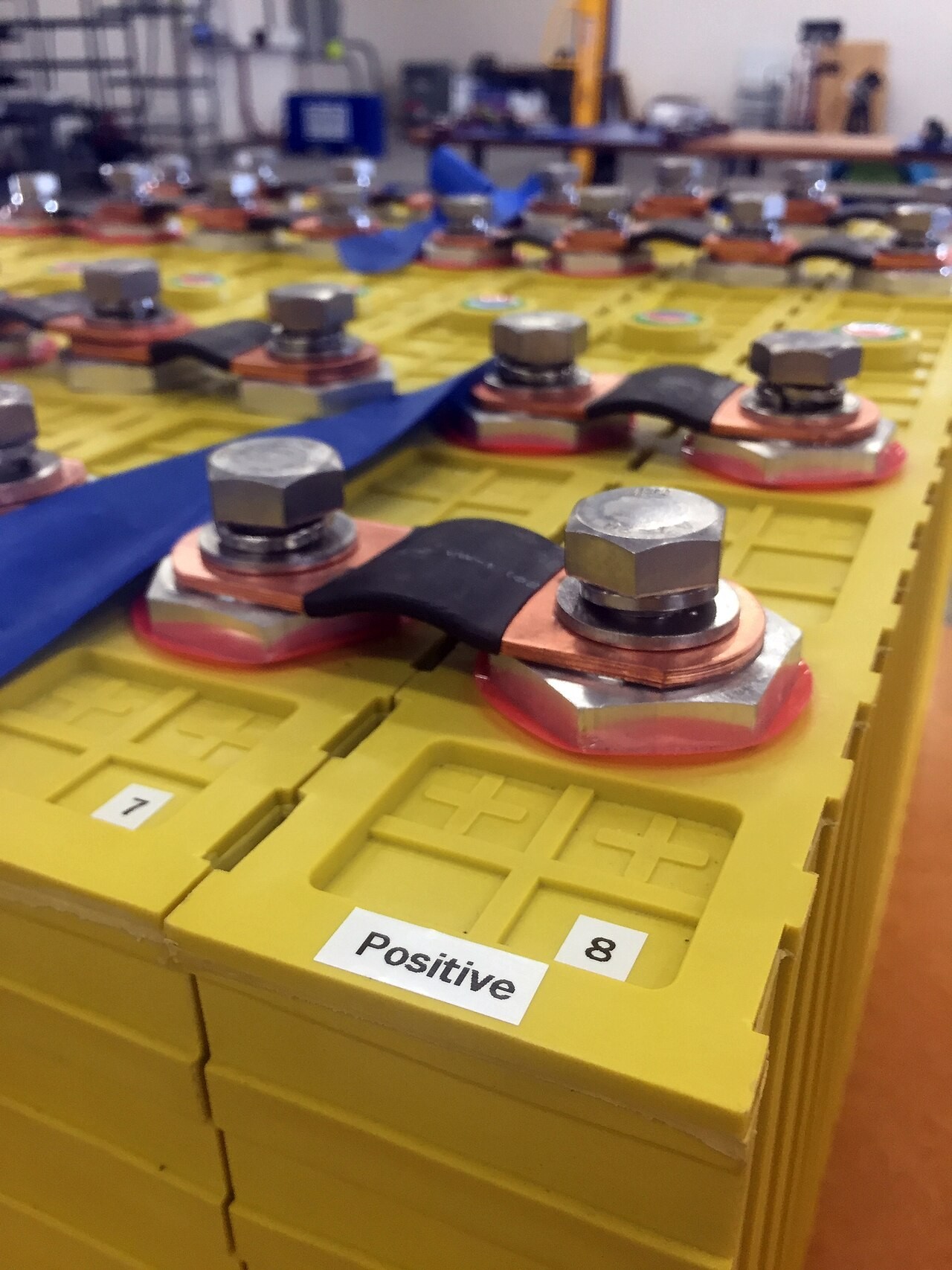
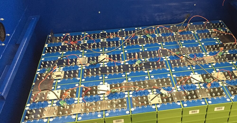
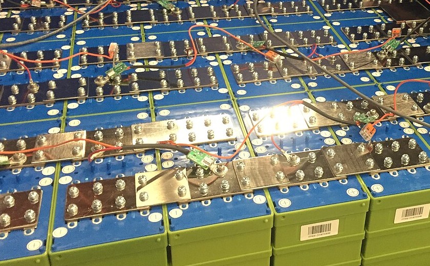
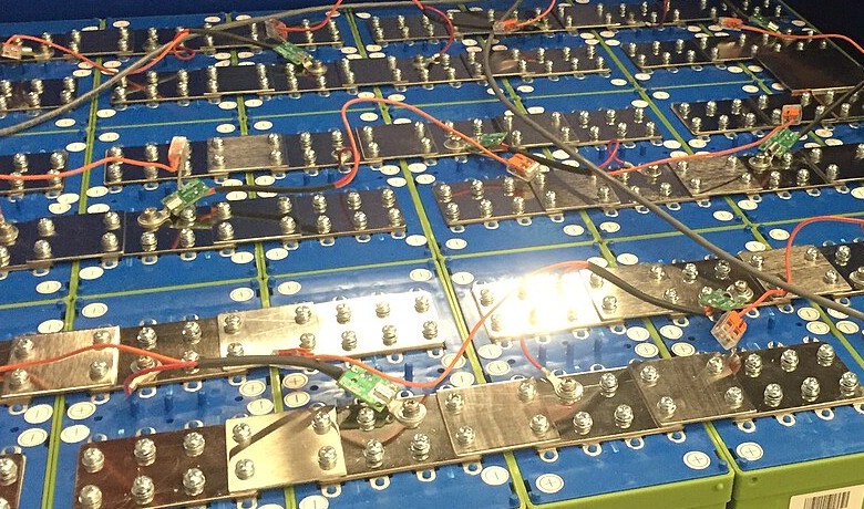
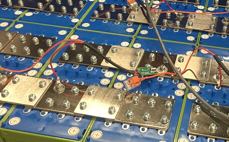
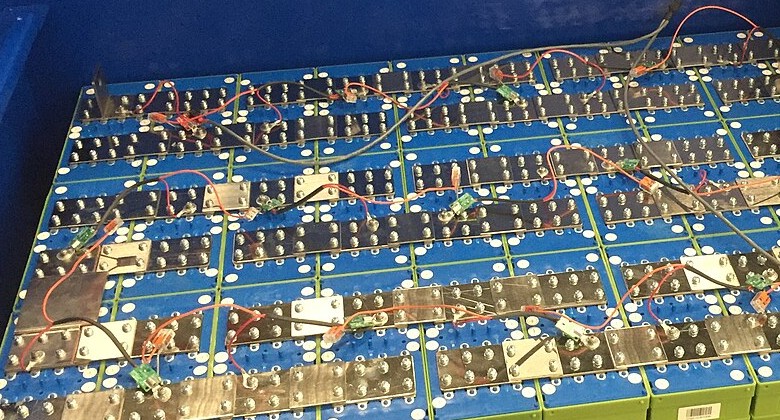
Cell Balancing
No manufacturing process gives identical cells. Capacity variations of a few percent between cells from the same production batch are typical. Internal resistance varies by similar margins. Differences compound during cycling as cells age at different rates depending on their individual thermal histories and state-of-charge excursions.
Series connection amplifies consequences of cell variation. During charging, cells with lower capacity reach voltage limits first, terminating charging for the entire pack while higher-capacity cells remain partially charged. During discharge, lower-capacity cells reach cutoff voltage first, stopping discharge while higher-capacity cells retain usable energy. Both mechanisms reduce pack capacity to match the weakest cell.
Modern battery management systems continuously monitor and balance individual cell voltages
Passive balancing dissipates excess energy from higher-voltage cells through resistors. Balancing current, typically 50-200mA in consumer-grade systems, bleeds charge from cells that reach voltage limits while other cells continue charging. Energy wastes as heat. Process proceeds slowly, requiring hours to correct significant imbalances.
Active balancing transfers charge from higher-voltage to lower-voltage cells through capacitive or inductive circuits. Energy captured from one cell recharges another rather than converting to waste heat. More rapid and efficient but costs more.
Balancing circuit quality often distinguishes quality batteries from cheap alternatives more reliably than cell quality itself. Budget batteries may employ minimal balancing with 20-50mA current, insufficient to correct developing imbalances before they accelerate cell degradation.
Discharge
Discharge reverses charging. Lithium ions depart from graphite intercalation sites, traverse electrolyte, and reinsert into LiFePO4 cathode. Electrons flow through external circuits from anode to cathode.
Discharge voltage reflects chemical potential difference between lithium in its anode and cathode environments. Potential difference remains nearly constant throughout most of discharge because two-phase reaction mechanisms in both electrodes maintain constant chemical potential within each electrode. Voltage changes rapidly only when one phase disappears near complete charge or discharge.
Flat discharge curves distinguish LiFePO4 from other lithium chemistries and from all lead-acid variants. A 12V LiFePO4 battery maintains voltage between 13.0V and 12.8V from 90% to 20% state of charge. Lead-acid batteries show continuous voltage decline throughout discharge.
Battery terminal voltage during discharge falls below open-circuit voltage due to internal losses collectively termed polarization. Ohmic polarization: instantaneous voltage drop proportional to discharge current from resistance in current collectors, tabs, electrolyte, and interfaces. Charge transfer polarization reflects activation energy required for electrochemical reactions at electrode surfaces. Concentration polarization emerges when lithium transport within electrodes or electrolyte cannot sustain demanded current.
Combined effects reduce practical battery capacity at high discharge rates. A 100Ah battery discharged at 1C may deliver only 90-95Ah before reaching cutoff voltage. Discharging at 0.2C recovers nearly full rated capacity.
Deep Discharge Damage
Discharging below recommended cutoff voltage (10.0V for a 12V pack, 2.5V per cell) initiates damage that may prove irreversible.
Copper dissolution from anode current collectors becomes thermodynamically favorable below around 2.5V versus lithium. Copper foil serving as anode current collector begins oxidizing and dissolving into electrolyte. Dissolved copper ions migrate through electrolyte and deposit on the cathode, partially short-circuiting the cell.
Cathode over-lithiation at very low voltages drives lithium content beyond stable LiFePO4 stoichiometry. Excess lithium distorts olivine frameworks, potentially breaking iron-oxygen bonds and releasing iron into electrolyte.
SEI may partially dissolve or restructure during deep discharge. Subsequent charging must reform SEI, consuming additional lithium inventory.
Recovery possible in some cases. Batteries discharged below cutoff voltage may appear dead but often retain recoverable capacity. Quality BMS systems include recovery modes that apply gentle charging current to deeply discharged cells. Cells discharged to 2.0V for minutes may recover fully. Cells held at 1.5V for days likely sustain permanent damage. Cells discharged below 1.0V rarely recover usefully.
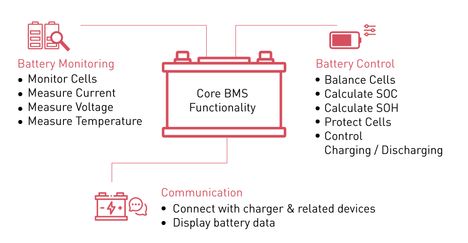
Battery Management Systems
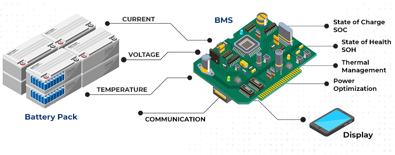
BMS prevents operation outside safe parameters through continuous monitoring and rapid response. Modern platforms integrate voltage sensing, current measurement, temperature monitoring, and communication interfaces.
Battery management systems integrate sophisticated electronics for real-time monitoring and protection
Voltage sensing requires per-cell measurement with accuracy adequate to detect developing imbalances before they damage cells. Measurement accuracy of 5-10mV permits detection of nascent cell divergence. Lower accuracy allows imbalances to develop undetected until they manifest as premature capacity loss.
Current sensing employs either Hall effect sensors or precision shunt resistors. Hall sensors measure magnetic field around a conductor, providing galvanic isolation between power path and sensing circuit.
Overvoltage protection activates at 3.65V per cell, interrupting charge current through MOSFET switches within 10-100 milliseconds. Undervoltage protection engages at 2.5V per cell. Some systems implement two-stage undervoltage protection: a warning threshold at 2.8V triggers load reduction or alerts while a hard cutoff at 2.5V disconnects all loads. Overcurrent protection responds to sustained excessive current by reducing or disconnecting output. Short circuit protection requires sub-millisecond response; dedicated analog comparators bypass digital processing to achieve response times below 100 microseconds. Temperature protection prevents charging below 0°C and above 45°C.
State of charge and state of health cannot be measured directly. Coulomb counting integrates current over time to track charge flow but accumulates drift errors. Open-circuit voltage provides ground truth through the relationship between rest voltage and lithium content, but flat voltage plateau of LiFePO4 reduces sensitivity between 20% and 80% state of charge. Kalman filtering combines both approaches, using voltage measurements to correct coulomb counting drift.
A note on BMS reliability: the protection circuits themselves can fail. MOSFET failures tend toward short-circuit, meaning a failed protection switch may leave the battery unprotected rather than disconnected. Some field failures attributed to "cell defects" actually trace to BMS component failures that allowed operation outside safe parameters until cells were damaged. Quality battery systems include redundant protection paths. Budget systems often lack redundancy, relying on single components that become single points of failure.
Degradation
Understanding degradation mechanisms transforms battery management from guesswork into informed decision-making.
Calendar Aging
Batteries degrade continuously from the moment of manufacture regardless of use.
SEI growth dominates calendar aging in graphite anode batteries. SEI never achieves perfect passivation; electrolyte decomposition continues at a slow rate that increases with temperature and state of charge. Storage temperature has dramatic effects: degradation at 45°C proceeds three to four times faster than at 25°C.
Temperature sensitivity follows Arrhenius kinetics, with surprising practical implications. A battery stored in a hot garage in Arizona degrades faster sitting unused than a battery cycled daily in a climate-controlled Minnesota basement. Users who purchase batteries and store them "for emergencies" often discover their emergency capacity has evaporated by the time they need it.
Optimal Storage Conditions
State of charge during storage matters nearly as much as temperature. High state of charge means high electrode potentials, which accelerate parasitic reactions. A fully charged battery stored at 25°C degrades roughly twice as fast as the same battery stored at 50% charge. Combined with temperature effects, a fully charged battery in a hot environment can lose substantial capacity within a single summer. Optimal storage: 10-15°C and 40-60% state of charge.
Cathode degradation contributes through transition metal dissolution, structural degradation at particle surfaces, and parasitic reactions with electrolyte impurities.
Cycle Aging
Repeated charge-discharge cycles impose mechanical stress that eventually degrades electrode structures regardless of electrical parameter control.
Volume changes during lithiation and delithiation strain electrode particles. Graphite expands roughly 10% along its c-axis during full lithiation, stressing interfaces between graphite particles and the conductive carbon and binder matrix. Repeated expansion and contraction fatigues these interfaces, eventually isolating active material from current collectors.
Understanding cycle aging helps optimize battery systems for maximum operational lifespan
The isolation mechanism proceeds gradually but accelerates once it begins. Initial crack formation exposes fresh electrode surface to electrolyte, triggering new SEI formation that consumes lithium. New SEI mechanically bridges some cracks, restoring partial connectivity. But repeated cycling reopens healed cracks and creates new ones. Eventually the damage rate exceeds the healing rate and capacity loss accelerates.
Particle fracture accelerates with depth of discharge. Cycling between 20% and 80% state of charge imposes less than half the strain amplitude of 0-100% cycling. Halving depth of discharge roughly doubles cycle count to a given end-of-life criterion.
SEI evolution during cycling adds to mechanical degradation. Volume changes at graphite surfaces stretch and compress SEI, exposing fresh graphite to electrolyte decomposition.
Temperature Effects
Temperature influences degradation rates more strongly than any other operational parameter.
High temperature operation accelerates both calendar and cycle aging. Electrolyte decomposition reactions proceed faster. SEI stability decreases. Transition metal dissolution from cathode materials increases. Operating at 45°C instead of 25°C may halve battery lifetime.
Low temperature operation brings distinct damage. Reduced electrode kinetics increase plating risk during charging. Mechanical stress from temperature-induced contraction adds to cycling strain. Electrolyte viscosity increase reduces ionic conductivity.
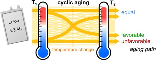
Temperature cycling itself causes damage independent of the temperatures involved. Differential thermal expansion between cell components creates mechanical stress at interfaces. Cells that experience large daily temperature swings age faster than cells held at constant temperature, even if the average temperature equals the constant-temperature case.
Diagnosing Degradation
Determining why a battery has lost capacity helps predict future behavior and informs decisions about continued use versus replacement.
Capacity loss accompanied by dramatically increased internal resistance usually indicates SEI growth or electrode isolation. The battery may still function acceptably for low-current applications despite failing under high loads.
Capacity loss with relatively preserved internal resistance suggests lithium inventory depletion, either through SEI formation or lithium plating. If plating caused the loss, continued degradation will be rapid. If SEI growth caused it, degradation rate should remain roughly constant.
Sudden capacity loss after months of stable operation often indicates mechanical failure: a weld breaking, a current collector cracking, or a cell-to-cell connection failing. BMS data showing one cell diverging from others points toward this diagnosis.
Gradual capacity loss that accelerates over time suggests compounding damage, often from operation outside recommended parameters. The acceleration indicates ongoing damage mechanisms that will continue.
One diagnostic technique that reveals much about battery condition: measure capacity at two different discharge rates. A battery showing 95Ah at 0.2C but only 70Ah at 1C has developed significant internal resistance, likely from SEI growth or electrode isolation. A battery showing 80Ah at both rates has lost lithium inventory but retains low internal resistance, suggesting calendar aging rather than abuse-related damage. The ratio of high-rate to low-rate capacity provides more diagnostic information than either measurement alone.
Solid-State Electrolytes
Solid-state electrolytes have attracted enormous research investment as potential successors to liquid electrolyte systems.
Solid electrolytes eliminate flammable organic solvents responsible for fire risk in liquid electrolyte batteries. Ceramic and polymer solid electrolytes cannot ignite or generate flammable vapors under any conditions.
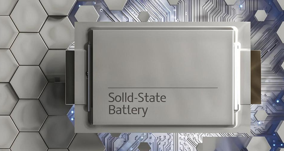
Solid-state battery research continues in laboratories worldwide, though commercial deployment remains elusive
Energy density improvements would come from lithium metal anodes. Liquid electrolytes permit dendrite growth that eventually penetrates separators, but certain solid electrolytes mechanically suppress dendrite formation through their rigidity. Lithium metal anodes provide roughly ten times the capacity of graphite.
Interface resistance between solid electrolyte and electrode materials remains the central obstacle. Liquid electrolytes wet electrode surfaces intimately, providing ionic contact over the entire interface. Solid-solid interfaces achieve contact only at points where surfaces happen to touch. Manufacturing processes that achieve adequate interfacial contact at scale do not yet exist.
Commercial deployment timelines have repeatedly slipped. Solid-state batteries have been "five years away" for at least fifteen years. The technical problems are real and difficult. Anyone claiming imminent commercialization of solid-state 12V batteries either misunderstands the challenges or is selling something.
Applications
Solar and wind energy storage matches LiFePO4 characteristics well. Daily cycling pattern aligns with battery capabilities. 90% depth of discharge capability versus 50% for lead-acid effectively doubles storage capacity per unit installed. Charge controller selection requires lithium-specific programming; lead-acid algorithms will damage lithium batteries.
An observation from solar installations: batteries positioned where afternoon sun heats the enclosure degrade noticeably faster than identical batteries in shaded locations, even when both experience similar average temperatures. Peak temperature matters more than average temperature for degradation kinetics. A battery that reaches 50°C for two hours daily degrades faster than one held constantly at 35°C, despite the second experiencing higher average temperature over a 24-hour period. Installation planning should consider peak temperatures, not just averages.
Mobile applications benefit dramatically from lithium's superior energy density and cycle life
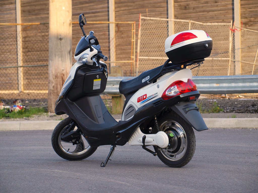
Mobile applications present environmental challenges including vibration, temperature variation, and extended storage periods. A 100Ah LiFePO4 battery weighing 12-15 kg replaces lead-acid capacity requiring 30-35 kg. No maintenance required.
Backup power applications benefit from long standby life. A quality LiFePO4 battery in float service may retain 80% capacity after a decade, compared to three to five years for VRLA batteries.
Purchasing
The 12V LiFePO4 market contains products ranging from excellent to fraudulent.
BMS specifications distinguish quality products from budget alternatives. Balancing current, protection thresholds, and communication capabilities reveal design intent. Budget batteries often pair decent cells with inadequate management systems that allow premature failure.
Warranty terms reveal manufacturer confidence. Five-year warranties with clear capacity retention guarantees suggest quality. One-year warranties or vague language suggest otherwise.
Cell origin affects quality more than most buyers realize. Cells from established manufacturers with documented production processes outperform anonymous cells from contract manufacturers optimizing solely for cost.
Manufacturing quality and rigorous testing distinguish premium batteries from budget alternatives
Thermal design receives insufficient attention in many products. Batteries with provisions for temperature sensing, thermal insulation, or active cooling outperform those treating thermal management as an afterthought.
Price premiums for quality batteries repay themselves through longer service life. A battery lasting eight years at 30% higher initial cost outperforms a battery lasting four years. Calculations become more favorable when installation labor and system downtime enter the equation.
One purchasing observation that has proven reliable: manufacturers who publish detailed BMS specifications, cell source information, and test data generally produce better batteries than those who publish only headline capacity and vague "long life" claims. Transparency correlates with quality. Manufacturers hiding specifications usually have something to hide.
Another pattern: batteries sold through marine and RV specialty channels typically outperform identically-priced batteries from general electronics retailers, even when specifications appear similar. The specialty channels have reputation stakes and customer bases that demand durability. General retailers face price pressure that incentivizes corner-cutting on components that do not appear in marketing specifications.
12V lithium batteries operate through electrochemical processes established decades ago. Cell quality has improved, manufacturing costs have decreased, management systems have grown more sophisticated. Fundamental mechanisms of lithium intercalation, ion transport, and electrochemical reaction remain unchanged. Better batteries will emerge from continued refinement of these mechanisms. Revolutionary alternatives remain perpetually on the horizon.