


A lithium battery charger delivers power through two distinct phases. During constant current mode, steady amperage flows as voltage climbs toward the cell's electrochemical limit. Once voltage reaches that ceiling, the system transitions to constant voltage regulation, holding output at the threshold as current decays exponentially.
Deviation from this protocol accelerates degradation. Float charging, which sustains lead-acid batteries through continuous low-voltage maintenance, causes cumulative damage to lithium cells.
The Core Mechanism: How Lithium Battery Chargers Convert Power
Ion migration drives the charging process. When charger output exceeds the battery's open-circuit voltage by adequate margin, ions depart cathode intercalation sites, traverse the electrolyte barrier, and embed themselves within the anode's graphite layers.

Power conversion begins at the AC inlet. A bridge rectifier flips negative half-cycles positive, producing pulsating DC with 120Hz ripple. Switch-mode power supply topology reshapes this waveform by chopping it at high frequencies through MOSFET transistors. Linear power supplies still appear in low-power consumer applications, but above modest power levels the heat dissipation becomes prohibitive—a linear supply delivering 50 amperes at 14.6V from an 18V DC bus wastes 170 watts as heat.
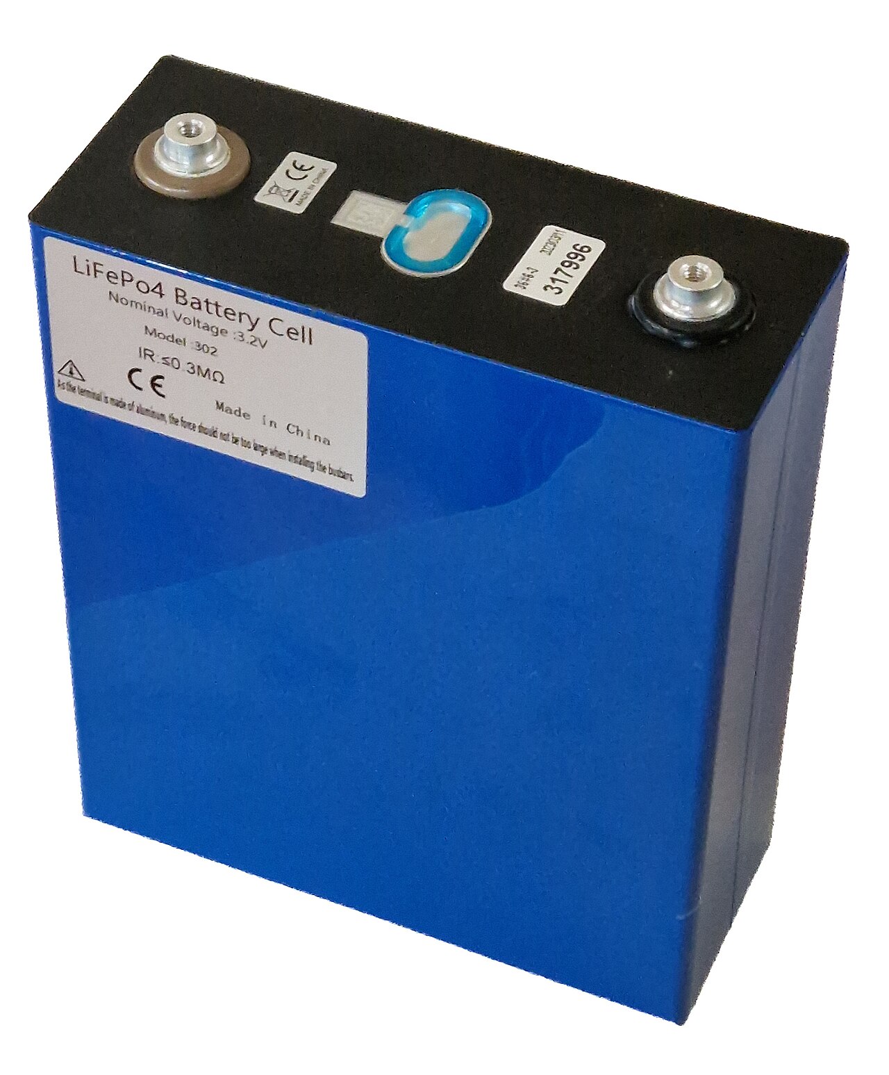
Output voltage for a 12V lithium battery charger must land between 14.2V and 14.6V depending on chemistry: 14.6V for LiFePO4, 14.4V for lithium-ion with graphite anodes, 11.0V for lithium titanate. Exceeding 14.6V on a LiFePO4 pack initiates electrolyte oxidation at the cathode surface, and gas generation begins as internal pressure rises.
During constant current mode, a 100Ah battery charging at 0.5C receives 50 amperes. Negative feedback control operating thousands of times per second maintains current stability, with internal operating voltage rising to compensate as battery voltage climbs.
Once cell voltage contacts the maximum safe limit, output locks at that ceiling and current decay follows exponential mathematics dictated by lithium-ion diffusion coefficients within electrode materials.
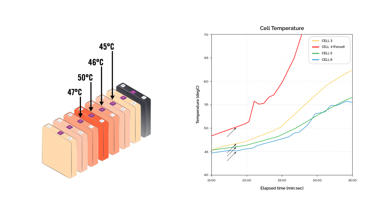
Thermistors bonded to cell surfaces feed continuous readings to the microcontroller. Current reduces as readings approach 45°C. Charging suspends entirely above 50°C or below 0°C. Below freezing, lithium plates on the anode surface rather than intercalating into graphite, consuming active lithium inventory permanently and creating dendritic structures capable of penetrating separators.
Inside the Charger: Key Components and Their Functions
At the heart of every lithium charger sits a microcontroller. An 8-bit processor sampling voltage and current 50 times per second struggles to track rapid transients during phase transitions. 32-bit ARM Cortex-M processors handle this better.
Synchronous buck converters eliminate Schottky diode losses by substituting a low-side MOSFET for the freewheeling diode. At 50 amperes, a Schottky dissipates 15 to 25 watts; a 3-milliohm MOSFET dissipates 7.5 watts. Synchronous designs introduce shoot-through risk—if both MOSFETs conduct simultaneously during switching transitions, even briefly, the resulting current spike can destroy both devices. Texas Instruments dedicates three pages in the LM5116 datasheet to dead-time optimization alone, specifying propagation delay matching within 5 nanoseconds and adaptive dead-time circuits that respond to load current.
Gate driver selection interacts with MOSFET gate charge characteristics. A FET with 40nC total gate charge driven by a 2A gate driver switches in 20 nanoseconds. With a 0.5A driver, the same FET takes 80 nanoseconds, during which switching losses accumulate. Thermal design must account for these losses concentrating in the FET die during each transition. Inductor selection involves similar tradeoffs—higher switching frequencies reduce ripple but increase losses, and the 2.2μH value needed for 100kHz costs three times more than the 4.7μH suitable for 50kHz. Cheaper chargers stick with asynchronous designs because complexity drops significantly.
Current sensing relies on precision shunt resistors. Budget designs use resistors with wide tolerance bands that introduce measurement errors. A 1-milliohm shunt sensing 50 amperes produces only 50mV, demanding a low-offset instrumentation amplifier like the INA181 or AD8418 to achieve usable accuracy. Vishay's WSL2512 series maintains 1% tolerance with a 75ppm/°C temperature coefficient. For higher precision, Bourns' CSS2H-2512 offers 0.5% tolerance.
Hall-effect sensors eliminate the shunt's power dissipation entirely and offer galvanic isolation—a significant advantage in high-voltage systems.
Allegro's ACS758 series handles currents up to 100A. But Hall sensors exhibit 1.5% typical accuracy at best, and their output drifts with temperature. For detecting CV-mode charge termination thresholds where current has dropped to 3-5% of the CC-mode value, Hall sensor accuracy falls short. Shunt-based sensing remains dominant for precision charging.
CAN bus dominates professional charger-BMS communication because differential signaling tolerates electromagnetic interference. SAE J1939, originally developed for heavy trucks, has become the standard for lithium battery systems in marine, RV, and industrial applications. Victron, Mastervolt, and Sterling Power all use J1939 variants running at 250 kbit/s—fast enough for the 100ms update cycles that battery management requires.
Protection circuits should operate independently of the microcontroller. Hardware comparators trigger shutdown within microseconds if voltage exceeds thresholds. Texas Instruments' TPS2660 integrates overcurrent, overvoltage, and reverse-polarity protection in a single device rated for 60V and 5A continuous. For higher currents, discrete protection using comparators like the LM339 driving high-side switches provides more flexibility. Chargers relying solely on software protection occasionally fail in ways that damage batteries. A firmware hang or watchdog failure should not result in a battery fire.
The Two-Stage Charging Process Explained
When a depleted battery contacts the charger output, constant current mode begins. A 200Ah battery receiving 100 amperes accumulates 100Ah during the first hour. Starting from 20% state-of-charge, this single hour brings the battery to 70% capacity. The CC phase occupies roughly 90 minutes. The CV phase requires 45-60 additional minutes.
Starting from full CC current, amperage drops significantly within the first 15 minutes of CV mode, then slows. Lithium ions entering the anode must migrate from electrode surface into graphite bulk through interstitial pathways within the crystal structure. Heat generation raises cell temperature several degrees above ambient. A battery that runs hot during charging when identical batteries nearby stay cool indicates a potential problem. Progressive Dynamics' PD9260CV runs LiFePO4 packs warm because its CV voltage sits at 14.6V with no temperature derating. Victron's Blue Smart IP22 allows adjustment down to 14.2V.
Voltage Requirements Across Different Systems
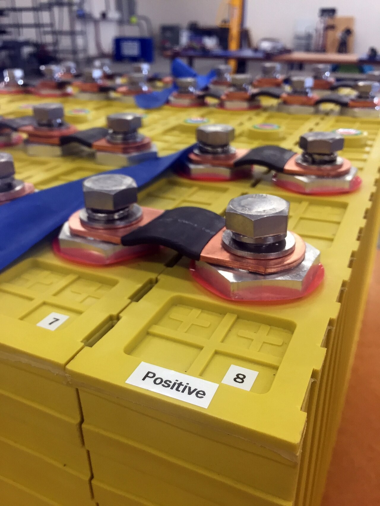
A 12V lithium system comprises four cells in series, each operating between 2.5V depleted and 3.65V charged. Output at 14.5V leaves cells slightly undercharged; 14.7V overstresses cathode materials and triggers BMS protection. RV and marine applications standardize on 12V for compatibility with existing lead-acid infrastructure.
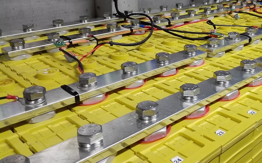
Eight cells produce 24V charging to 29.2V; sixteen cells produce 48V charging to 58.4V. Higher voltage means lower current for the same power. Victron's Quattro 48/10000 handles 48V banks up to 800Ah at 140A charging current. The same 6.7kW at 12V would require 560A.
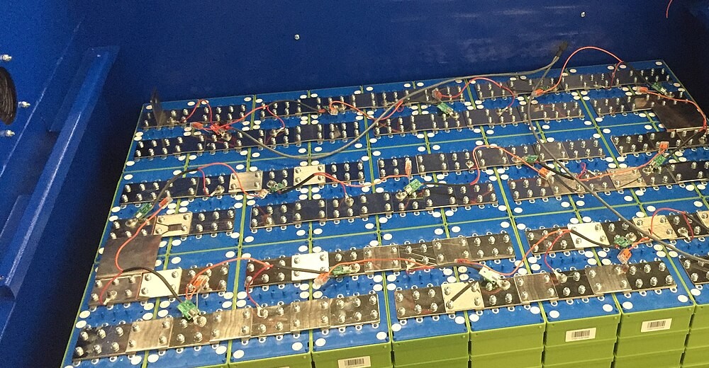
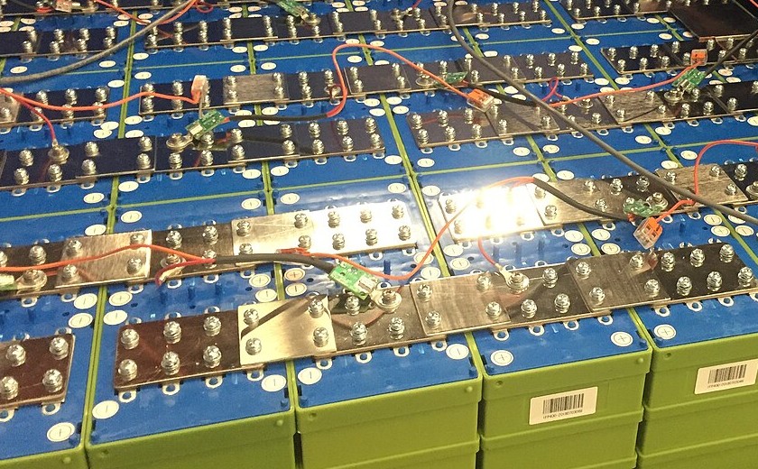
Cells from the same production batch still exhibit capacity differences. Lower-capacity cells reach full charge first and continue absorbing current that raises voltage above optimal levels. In a 16S pack this imbalance may require balancing intervention. Ewert Energy's Orion BMS samples individual cell voltages 10 times per second and communicates charge current limits via CAN bus. Passive balancing through resistive bleed wastes energy and takes hours—a 48V pack with 100mV cell imbalance and 68-ohm balance resistors needs over 4 hours to equalize. Active balancing using inductor-based charge shuttling works faster but costs 5-10x more.
Why Regular Lead-Acid Chargers Damage Lithium Batteries
Lead-acid charging culminates in float mode, maintaining 13.2-13.5V continuously to counteract self-discharge. Lithium batteries self-discharge far less and require no float compensation. Float voltage appropriate for lead-acid causes gradual degradation in lithium by holding cells at elevated potential. LiFePO4 batteries should rest at 13.2-13.4V when full. Sustained higher float voltage accelerates electrolyte decomposition, consumes lithium inventory through parasitic side reactions, and degrades cathode crystal structure. Several months of float charging can reduce capacity measurably. Battle Born publishes a technical bulletin citing customer returns with 15-20% capacity loss after extended float charging.
Lead-acid chargers also implement wide voltage tolerance bands—a charger rated for 14.6V might deliver anywhere from 14.1V to 15.1V. Lithium needs tighter precision.
NOCO's Genius series advertises lithium modes, but several models still apply a 13.6V float after completing the charge cycle. Renogy's DCC50S allows user-programmable float voltage down to 13.2V.
Temperature compensation creates another mismatch. Lead-acid chargers reduce voltage as temperature rises above 25°C to prevent gassing and water loss. Cold lithium batteries present higher internal resistance and benefit from elevated voltage—the opposite behavior. The typical lead-acid compensation coefficient of -3mV/°C per cell means a 12V charger reduces its output by roughly 72mV at 31°C, which does nothing useful for lithium and slightly undercharges the pack.
Lead-acid batteries also require extended absorption time because sulfation reversal proceeds slowly. Lithium cells complete CV phase in 30-60 minutes, so a lead-acid charger programmed for 3-hour absorption continues forcing current well beyond completion. The excess current generates heat and stress without adding usable capacity.
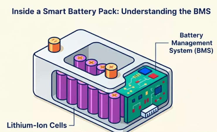
Modern lithium batteries depend on BMS circuits monitoring individual cell voltages, pack temperature, and current flow. These systems communicate through protocols that lead-acid chargers cannot interpret. The BMS may disconnect because a single cell reached voltage limit even as pack voltage suggests headroom. The charger attempts reconnection. The BMS disconnects again. Repeated reconnection attempts under load accelerate contact wear and can damage output capacitors through inrush current stress. Morningstar's TriStar MPPT addresses this with a 30-second reconnection delay and current-limited soft-start when BMS disconnection is detected.
Charging Rate, Temperature, and Lifespan Engineering
Batteries charged at lower C-rates outlast those charged aggressively. Reducing from 1C to 0.5C yields noticeable lifespan improvement. Further reduction to 0.3C helps less. Below 0.2C, extended charging time costs more in convenience than it saves in battery wear.
Temperature matters just as much. A battery running warm ages faster than one kept cool. Nissan Leaf degradation data from the early 2010s showed vehicles in Phoenix losing capacity nearly twice as fast as identical vehicles in Seattle with similar driving patterns.
At room temperature, lithium ions arriving at the graphite anode surface find intercalation sites readily available and slip between graphene layers.
Charging rates up to 1C can be accommodated without accumulation at the surface. When temperature drops below freezing, the intercalation reaction rate drops with it. Ions arrive faster than they can be absorbed into the graphite bulk and plate out as metallic lithium—not recoverable. Dendritic growths can extend into the electrolyte and penetrate the separator membrane to contact the cathode, creating an internal short circuit. The Samsung Note 7 fires in 2016 involved separator penetration, though from manufacturing defects rather than cold charging.
At 25°C, a well-designed cell sustains 1C charging with minimal plating because the intercalation reaction can keep pace with ion arrival. At 0°C and 0.5C, significant plating occurs because the reaction has slowed by a factor of roughly six. Waldmann et al. published data in the Journal of the Electrochemical Society in 2014 confirming plating onset at progressively lower C-rates as temperature dropped from 25°C to -20°C. Post-mortem analysis showed metallic lithium deposits increasing from undetectable at 25°C to 15% of transferred lithium at -10°C when charging at 1C. Petzl and Danzer at the Technical University of Munich later developed in-situ detection methods using voltage relaxation analysis, enabling real-time plating detection without destructive cell teardown.
A battery charged once at -5°C and 1C may lose 10-15% of its capacity permanently. The BMS should prevent this, but temperature sensors sometimes sit on the pack housing rather than on cells. A cold-soaked pack can show 5°C at the housing when cells remain below freezing. Electrodacus' SBMS0 places its temperature sensor directly on cell terminals, but many less sophisticated BMS units rely on a single thermistor mounted on the circuit board itself, several centimeters from the cells.
Some batteries incorporate resistive heating elements that warm cells before permitting charge initiation. Victron's Lithium Battery Smart series includes an internal heating element that draws 60W until cell temperature reaches 5°C. Battle Born offers similar heated models. Warming a 100Ah battery from -10°C to 5°C consumes roughly 2-3Ah.
Maintaining charge between 20% and 80% extends cycle life. High voltage at 100% accelerates cathode degradation through oxygen evolution from the crystal lattice and electrolyte oxidation at the cathode-electrolyte interface.
Deep discharge below 20% strains anode structures through excessive volume contraction and risks copper dissolution from current collectors into electrolyte.
Tesla implemented this principle. The default charge limit stops at 90% for daily driving, with 100% reserved for long trips. The Model S owner's manual states that keeping the charge level below 90% extends battery lifespan. Third-party data from Maarten Steinbuch at Eindhoven University tracking over 500 Tesla vehicles showed cars routinely charged to 100% lost capacity roughly 50% faster than those kept below 90%.

Batteries stored at 100% experience continuous voltage stress even without cycling. A battery stored at high SOC and elevated temperature loses capacity faster than one stored at moderate charge and cool temperature. Calendar aging data from NREL's Vehicle Technologies Office shows 50% SOC storage at 25°C retaining 95% capacity after 5 years, compared to 87% for 100% SOC storage. Battery manufacturers recommend 40-60% SOC for storage exceeding one month.
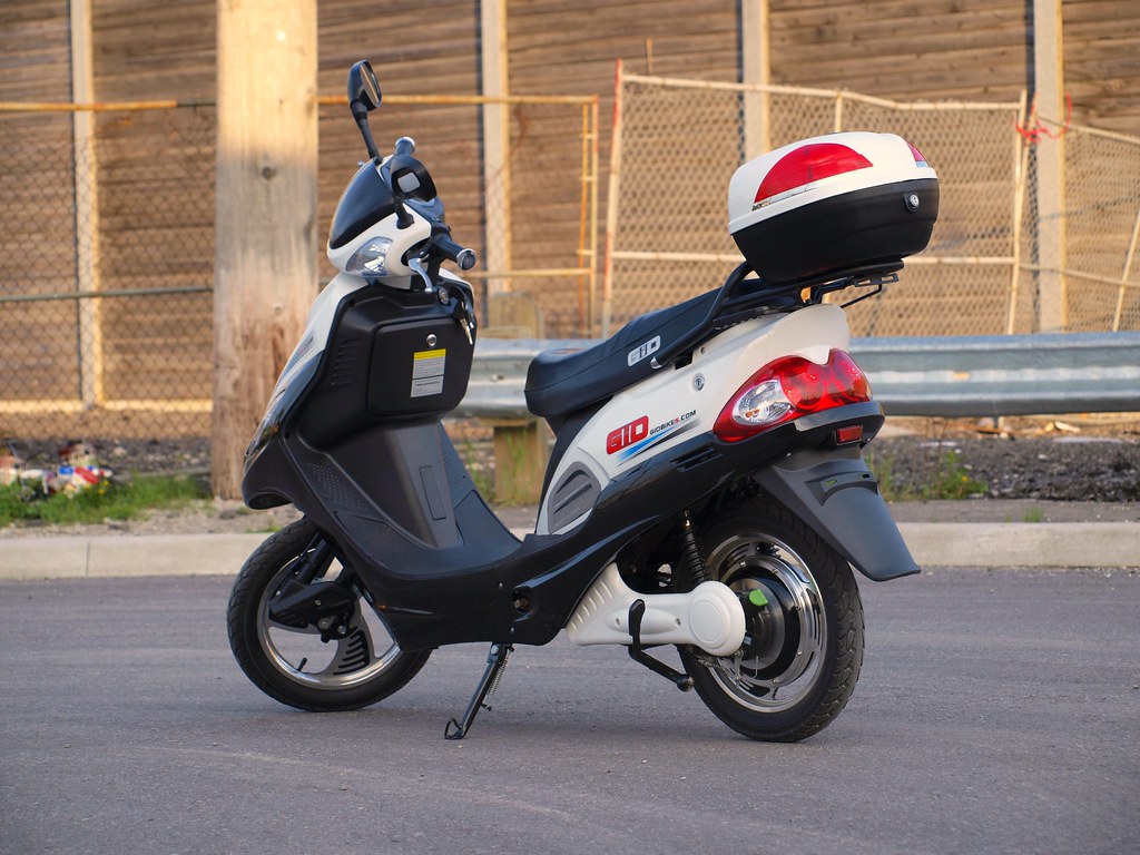
Aggressive charging degrades batteries faster, and the conservative approach requires no additional hardware. Many installations miss this because operators lack information about how parameters affect longevity, or because operational requirements prioritize speed. A rental e-bike fleet prioritizes rapid turnaround because batteries get replaced long before they wear out. A residential solar storage system with decades of expected service life operates differently.