Bipolar Transistors
Where Bipolar Transistors Still Fit
A bipolar junction transistor is a three-terminal device in which a small base current controls a much larger collector current. That current-controlled behaviour, set against the MOSFET’s voltage-controlled gate, defines what the BJT is and where it earns a place, since a handful of jobs suit a current-driven part and a low price better than a MOSFET does. The selection comes down to knowing those jobs, picking a part that costs almost nothing, and biasing it so it sits where the circuit needs it. The parts themselves are a short list of jellybean numbers a designer learns once and uses for a career, so the engineering is in matching the part to the role and getting the bias right, not in hunting through a catalog.
Why the BJT has not gone away
The MOSFET took the bulk of the high-current switching work years ago, so the BJT now holds the corners where its own current-driven behaviour suits the circuit better than a voltage-driven part. Knowing when a BJT still beats a MOSFET covers the low-cost signal switch, the linear stage, and the current source, where the BJT’s predictable forward voltage and its smooth transfer curve suit the job and its price undercuts the alternative. The BJT also turns on from a known base-emitter voltage near seven tenths of a volt, so a circuit can lean on that drop as a built-in reference for a current source or a simple temperature sensor, a behaviour a MOSFET’s spread of threshold voltages does not offer.
The clearest case is the small-signal amplifier. A BJT gives a high transconductance for the current it draws, so an analog stage gets gain from one cheap part without the input offset and the capacitance a small MOSFET brings, and a microphone preamp, a current mirror, or a bias generator still leans on it. The transconductance of a BJT is set by its collector current and a constant of physics, so two parts biased at the same current behave alike, which makes a current mirror built from a matched pair predictable in a way a MOSFET pair spread across its threshold is not. For a low-noise front end the BJT also brings a low voltage-noise floor at the modest source impedances an audio or a sensor stage presents.
Price is the other half. A general-purpose BJT costs a fraction of a cent in volume, so a board that needs a logic-level load switch, a level shifter, or an LED driver reaches for one in place of a part that costs more and does no better at the job. The current a small-signal BJT switches covers an indicator LED, a small relay, or a gate-drive boost stage, which is the band a great many everyday circuits sit in. Above that current the MOSFET takes over, so the BJT holds the low-current, low-cost end where its price decides the choice.
The part is also forgiving in ways that matter on a rough board.
A BJT has no static-sensitive gate to protect and no threshold that drifts between vendors, so it survives handling and substitution that a small MOSFET takes more care with, which is part of why the jellybean BJT stays in the parts library long after the MOSFET won the power sockets. A hand-soldered prototype or a high-volume line both handle the part without the static precautions a sensitive MOSFET gate demands, and a substitution between two vendors’ versions of the same part number drops in without a threshold surprise. For a hobby board, a teaching circuit, or a rugged industrial input, that tolerance is a quiet reason the part keeps its place.
Getting the bias right
A BJT does nothing useful until it is biased, so the resistors around it carry as much of the design as the part. Avoiding the common biasing mistakes in BJT selection starts with setting a stable operating point, since a stage biased straight off the base-emitter voltage drifts as that voltage falls with temperature and the collector current climbs with it.
That drift is the trap. The base-emitter voltage falls by about two millivolts for every degree the junction warms, so a current set by it rises as the part heats, the part warms further, and the current climbs again, the runaway that cooks an unstabilised stage. An emitter resistor that pushes back on the rising current holds the operating point, which is the fix the textbook bias network is built around. The resistor drops a voltage that rises with the collector current, and that voltage subtracts from the base drive, so a current that tries to climb is pulled back toward where the design set it. A voltage divider on the base sets a stiff reference, the emitter resistor sets the current, and the pair holds the operating point across temperature and across the wide spread of current gain from one part to the next.
The other common error is mixing up the regions. A switch driven into saturation behaves like a closed contact with a low voltage across it, and a stage meant to amplify has to stay in the active region where the collector current tracks the base current, so a design that drives an amplifier into saturation or leaves a switch half-on burns heat and loses the function it wanted. A switch is given enough base current to drive it hard into saturation for the lowest collector voltage and the least heat, and an amplifier is held in the active region by the bias network so a signal swings around the operating point without clipping. Confusing the two is the error behind a stage that distorts or a switch that runs hot, and the fix is reading the datasheet curve for the region the circuit needs.
The current gain itself is a number to design around, since it spreads widely from part to part and falls at low temperature and high current, so a robust circuit gives the base enough drive that the worst-case gain still does the job.
The jellybean parts
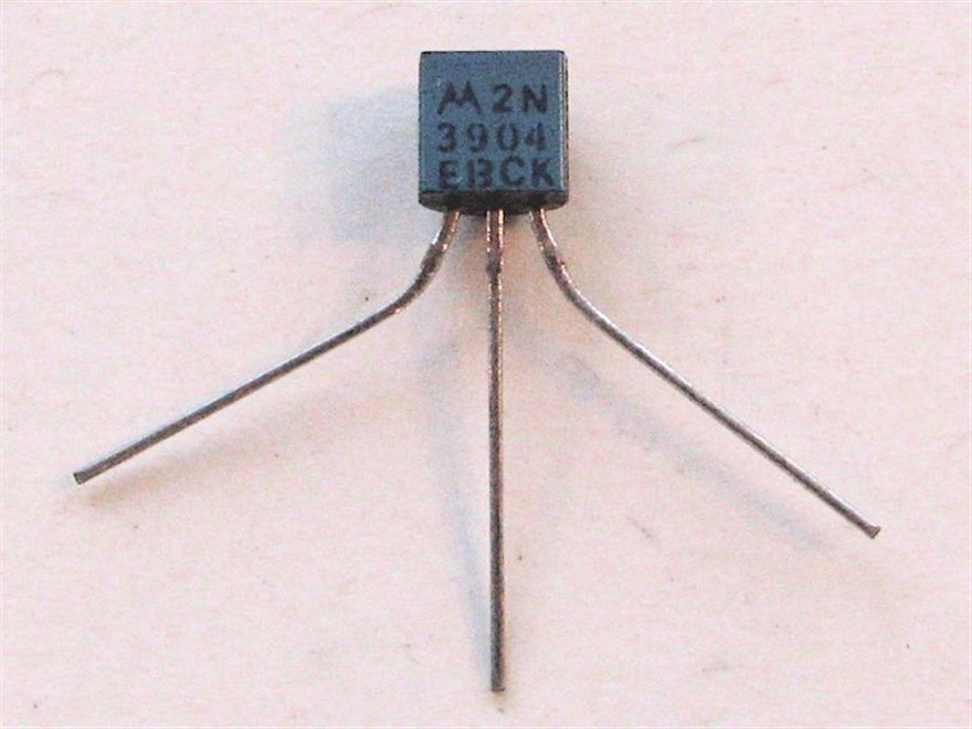
A few part numbers cover the bulk of small-signal needs. Understanding why the 2N3904 and 2N3906 stay must-stock parts comes down to a complementary NPN and PNP pair that handle a couple of hundred milliamps, cost almost nothing, and ship in every package from TO-92 to SOT-23, so a designer reaches for them without a second thought. The pair has been in production for decades, so the behaviour is documented in every textbook and the supply comes from a dozen makers, which keeps the price low and the stock deep. A part this well understood carries no surprises into a design, and a board that uses it inherits a half-century of application notes.
Europe brings its own pair. The sourcing and pricing of the BC547 and BC557 make them the default small-signal NPN and PNP across a large share of designs, with the same low price and broad stock that the part role demands.
One variant saves parts on a crowded board. Knowing how ROHM digital transistors save resistors covers the part with the base resistors built into the package, so a logic line drives it straight without the two external resistors a plain BJT switch needs, which clears board space on a dense layout. The built-in resistors set the input threshold and limit the base current, so a microcontroller pin drives the part directly into a clean on or off, and the saving of two passives per transistor adds up fast on a board that switches a dozen lines. The part comes in a range of built-in resistor values, so the design picks one matched to the logic voltage that drives it.
Where the Darlington still fits
Two transistors in one package give a gain the single part cannot, since the first transistor’s output current becomes the second’s base current and the two current gains multiply. Knowing where Darlington pairs still fit covers the high-gain, low-speed jobs like a relay or a small motor driver, where the multiplied current gain lets a weak signal switch a heavy load, at the cost of a higher saturation voltage from the two base-emitter drops in series and a slower turn-off that holds it to low frequencies. The classic relay-and-solenoid driver array packs seven Darlingtons in one part, so a microcontroller switches a bank of inductive loads through a single chip with the freewheeling diodes built in. The high saturation voltage means the part runs warm at high current, so a Darlington suits a load that switches now and then, and a hard-switched high-current rail goes to a MOSFET instead.
How BJTs get chosen and sourced
A BJT is read on its job: the collector current and voltage it handles, the current gain at that operating point, the package, and the price that makes it the easy choice over a MOSFET. A substitution among the jellybean parts is usually painless, since the 2N3904, the BC547, and their kin share a role and a pinout family, though the package and the pin order are checked because a TO-92 and a SOT-23 differ in lead arrangement. A broad-line distributor that carries the small-signal NPN and PNP pairs, the digital transistors, and the Darlingtons across the common packages keeps a board fed with parts that cost too little to second-guess.
The supply on these parts runs deep, since the jellybean transistors are made by many vendors to common specifications, so the sourcing concern is less about a single part going scarce than about holding the right package and pin variant for the footprint the board already uses. A 2N3904 in TO-92 and the same die as an MMBT3904 in SOT-23 carry different pinouts, so a board that moves from through-hole to surface mount confirms the lead arrangement against the new footprint. The cost is low enough that a design carries a generous stock and second-sources the part by its specification across several makers, so a shortage at one vendor rarely reaches the line. The deeper risk on these parts is a footprint or pinout mismatch on a redesign, which a quick check against the package drawing heads off.
The judgment that fits
Reach for a BJT where its current-driven behaviour and its price suit the job, bias it for a stable operating point with an emitter resistor against the temperature drift, and pick the jellybean part in the package the board wants. The six pages below take the parts and the design points one at a time.