IGBT Selection
IGBT Selection and Protection
An IGBT is a power switch that drives like a MOSFET and conducts like a bipolar transistor, taking a voltage-controlled gate that needs almost no steady drive current and pairing it with a low forward voltage drop that carries high current with little conduction heat. It earns its place at high voltage and high current, where a MOSFET of the same rating would burn more in conduction than the IGBT does. Choosing one is a matter of reading its conduction drop, its switching loss, and its safe operating area against the voltage, the current, and the frequency the design runs, and then building the gate drive and the protection that keep it alive when the load faults. The device and its drive are one design, since an IGBT picked well and driven badly fails as surely as the wrong part, and the bulk of the engineering on an IGBT stage sits in the gate drive and the fault handling, not the device line on the schematic.
What an IGBT is and where it fits
The device carries current with a roughly fixed voltage across it, the saturation voltage, so its conduction loss grows with the current and not with the square of it the way a MOSFET’s does. That makes the IGBT the cooler-running part once the current is high enough, since past a certain load the MOSFET’s resistive loss overtakes the IGBT’s fixed drop. The trade is at the switch-off, where the IGBT leaves a tail of current as its stored charge clears, and that tail is the loss that holds the device to low and middle switching frequencies.
The boundary is a real design decision. Finding the crossover point between an IGBT and a MOSFET comes down to the voltage class, the current, and the switching frequency together, since a MOSFET wins the low-voltage and high-frequency end on its fast, clean switching, and the IGBT wins the high-voltage, high-current end on its conduction drop. Above a few hundred volts and into tens of amps the IGBT is usually the part, and below that the modern MOSFET has taken ground the IGBT once held. The current matters as much as the voltage, since at a light load a MOSFET’s resistive drop stays small and the IGBT’s fixed saturation voltage wastes power for no gain, so the same 600 V stage can call for a MOSFET at a few amps and an IGBT at fifty. The wide-bandgap parts have pushed the line again, so a silicon-carbide device now reaches into territory that was IGBT-only a few years ago, and the crossover is read against what the budget allows as much as what the physics prefers.
Frequency sets the ceiling.
The tail current at turn-off fixes how fast an IGBT can switch before its switching loss swamps the heat budget, so a motor drive at a few kilohertz to twenty kilohertz suits the part and a converter at hundreds of kilohertz does not. The newer device generations have cut that tail and lifted the usable frequency, which is part of what separates one family from the next. A field-stop or trench design clears the stored charge faster, so a current-generation IGBT runs at a frequency an older planar part could not reach without cooking on its switching loss.
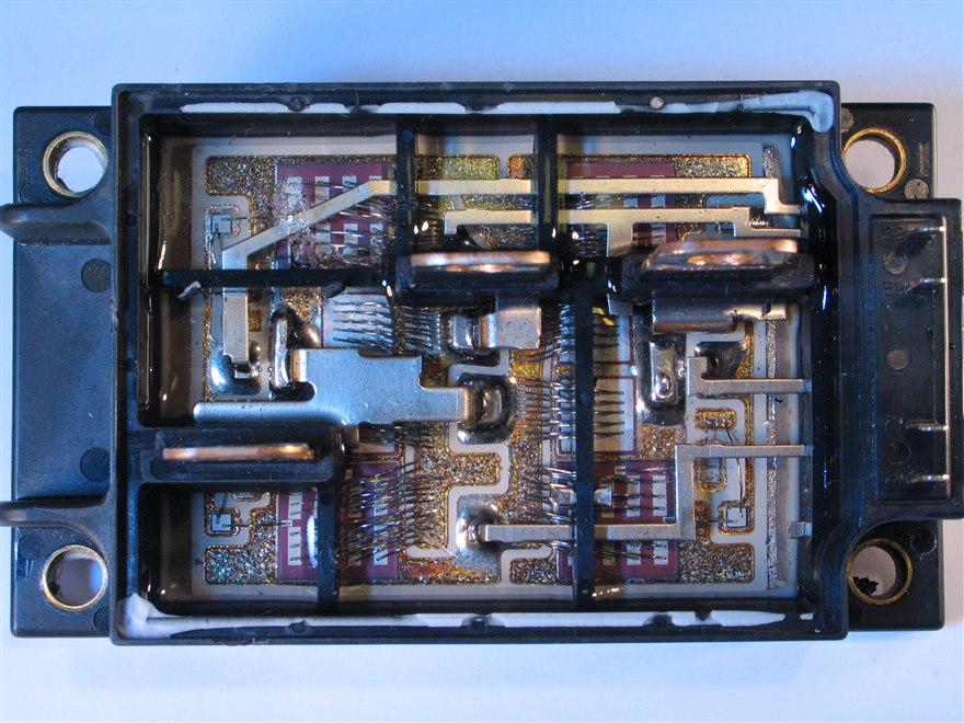
The modules and the families
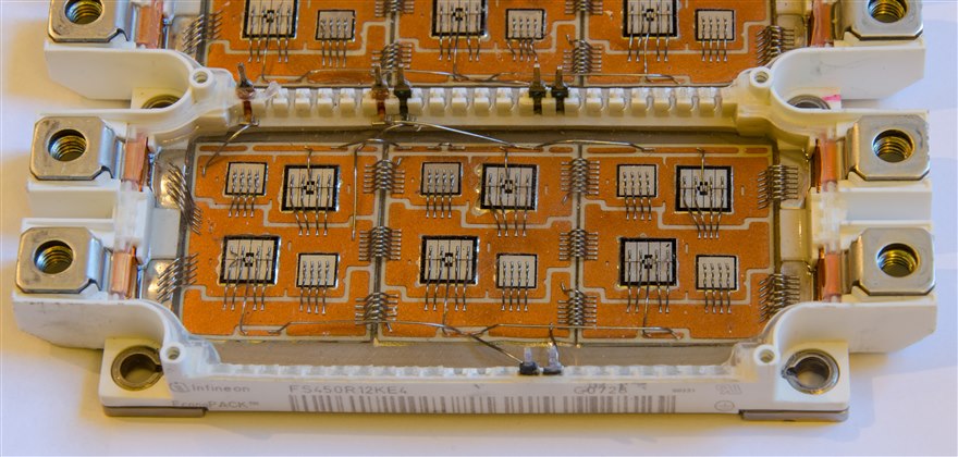
The package follows the power. For the high-current stages of a drive or an inverter, selecting an Infineon IGBT module covers the half-bridge and six-pack modules that carry tens to hundreds of amps with the dies, the diodes, and the thermal base in one housing, and the choice within that line often comes down to the chip generation. Comparing the Infineon TrenchStop 5 against the IGBT7 is a generation question, since the IGBT7 carries a lower saturation voltage and a higher rated junction temperature, and the older TrenchStop 5 stays specified where a design is already qualified around it. The newer chip runs a higher junction temperature, near 175 degrees against the older part’s 150, which buys headroom for the same heatsink or a smaller one for the same load, and its lower saturation voltage trims the conduction loss across the whole operating range. A requalification costs test time, so a running product earns the move only on a redesign or a real efficiency target.
Discrete parts fill the lower-power sockets. The adoption of the ON Semi NGTB IGBTs covers the discrete devices that suit a few-kilowatt stage, an induction hob, or a welder, where a TO-247 part on a heatsink does the job a module would over-serve. The grade and the co-packaged diode are read against the load the stage switches. A discrete part also asks the board to carry the gate drive, the sensing, and the heatsinking that a module integrates, so the saving on the device is weighed against the work it pushes onto the design.
The high-voltage end has its own parts. The Toshiba GT high-voltage IGBT applications reach the 600 V to 1200 V and higher classes that an industrial inverter, a UPS, or a traction stage needs, where the blocking voltage and the short-circuit ruggedness lead the selection. At these voltages the device has to hold off the rail with margin for the spikes a hard-switched inductive load throws back, and the part is read on its rated breakdown and its avalanche behaviour as closely as its current. A high-voltage IGBT also switches slower than a low-voltage one, so the frequency stays low and the conduction drop carries even more of the design’s weight.
Keeping the device alive
An IGBT fails fast when it is left unprotected, so the gate drive carries as much of the design as the device choice. The hardest fault to survive is a short across the load, and designing reliable IGBT short-circuit protection rests on desaturation sensing, where the driver watches the collector voltage and reads a rise during conduction as a short, since an IGBT carrying a fault current comes out of saturation and its collector voltage climbs. The part survives a short for only a few microseconds, so the driver has to detect that rise and turn the device off inside that window, and it has to do so softly, ramping the gate down rather than snapping it, because cutting a large fault current fast drives an inductive overshoot that can break down the device the protection was meant to save. The blanking time, the threshold, and the soft turn-off are tuned together so a normal turn-on transient does not read as a fault and a real short still trips in time. Once a fault has tripped, the driver reports it and holds the device off until the controller clears it, since switching back into a standing short would finish the part. The short-circuit withstand time is a device spec, so a part with a longer rating gives the protection more room to act and is the safer choice on a stage that sees rough loads.
The second hazard is the device turning itself on. Preventing IGBT false turn-on from the Miller effect matters in any half-bridge, since when one device switches on fast it throws a steep voltage step across the device opposite it, and that step couples through the gate-collector capacitance into the off device’s gate and can lift it past its threshold. A negative gate voltage at turn-off, a low gate-loop impedance, or an active Miller clamp holds the off device down, and skipping that step shows up as a shoot-through current that heats both devices for no work done. The faster the opposite device switches, the steeper the step and the worse the coupling, so the same move that cuts switching loss raises the false-turn-on risk, and the gate design balances the two. The negative rail is the common answer on a module, since it pulls the gate well below the threshold and holds it there through the worst step the bridge can produce.
The third concern shows up when one device is not enough.
Sharing current evenly across paralleled IGBTs lets a design reach a current no single device carries, and it leans on the saturation voltage rising with temperature, which pushes current away from the hotter device and toward the cooler one so the static balance is self-correcting. The dynamic balance during switching is harder, since a faster device takes more of the current at the transition, so the parts are matched, given their own gate resistors, and laid out symmetrically so each sees the same gate timing and the same stray inductance. Modules built for paralleling bring the dies into one package with that symmetry already designed in, which is the cleaner path where the current is high enough to need it. A design that parallels discretes derates the total below the simple sum, since no two devices share perfectly and the busiest one sets the limit.
The protection and the drive are not add-ons; they are designed with the device from the start.
How IGBTs get chosen and sourced
An IGBT is specified as a device, a co-packaged diode, a package thermal path, and a gate-drive and protection scheme together, so a substitution that keeps the voltage and current ratings can still fail if its saturation voltage, its short-circuit withstand time, or its switching loss differ. A broad-line distributor that carries the IGBT modules and discretes across the voltage classes and the major vendors lets a design source the device and a checked equivalent in the same footprint, and hold both the module and its matched gate driver in view. The thermal budget and the fault behaviour are the constants the selection answers to, since a device that runs cool and survives a short on one design can overheat or fail on another that drives it harder. A module ties the design to its footprint, since the pinout and the mechanical mounting differ between vendors, so a second source is qualified at the design stage, when an equivalent module can still be designed in, and a part that goes long on lead time mid-production is the kind of gap that stops a line.
The judgment that fits
Read the saturation voltage and the switching loss against the current and frequency, confirm the device sits in the IGBT half of the crossover, and design the gate drive with desaturation protection, a clamp against false turn-on, and matched parts if the stage parallels them.
The eight pages below take the families and the protection methods one at a time, from the Infineon, ON Semi, and Toshiba parts through short-circuit, Miller, and paralleling design.