Forklift Batteries
Forklift Solutions
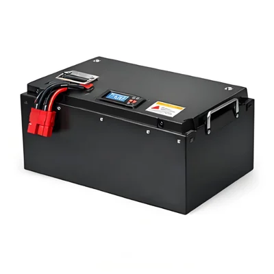
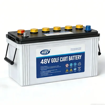
Golf Cart Batteries
Golf Cart Solutions
AGV & AMR Batteries
AGV Solutions
Pallet Jack Batteries
Pallet Jack Solutions
LFP Cells
All LFP Cells
3.2V 314Ah Cell
Prismatic LiFePO4 · 1004.8Wh
3.2V 320Ah Cell
Prismatic LiFePO4 · 1024Wh
3.2V 1.8Ah 18650 Cell
Cylindrical LiFePO4 · 5.76Wh
3.2V 3.4Ah 26650 Cell
Cylindrical LiFePO4 · 10.9Wh
3.2V 6Ah 32700 Cell
Cylindrical LiFePO4 · 19.2Wh
3.2V 15Ah 33140 Cell
Cylindrical LiFePO4 · 48Wh
3.2V 20Ah 40135 Cell
Cylindrical LiFePO4 · 64Wh
3.2V 173Ah Cell
Prismatic LiFePO4 · 553.6Wh
3.2V 202Ah Cell
Prismatic LiFePO4 · 646.4Wh
3.2V 230Ah Cell
Prismatic LiFePO4 · 736Wh
3.2V 280Ah Cell
Prismatic LiFePO4 · 896Wh
3.2V 302Ah Cell
Prismatic LiFePO4 · 966.4Wh
3.2V 72Ah Cell
Prismatic LiFePO4 · 230.4Wh
3.2V 86Ah Cell
Prismatic LiFePO4 · 275.2Wh
3.2V 100Ah Cell
Prismatic LiFePO4 · 320Wh
3.2V 125Ah Cell
Prismatic LiFePO4 · 400Wh
3.2V 150Ah Cell
Prismatic LiFePO4 · 480Wh
3.2V 105Ah Cell
Prismatic LiFePO4 · 336Wh
3.2V 20Ah Cell
Prismatic LiFePO4 · 64Wh
3.2V 32Ah Cell
Prismatic LiFePO4 · 102.4Wh
3.2V 40Ah Cell
Prismatic LiFePO4 · 128Wh
3.2V 50Ah Cell
Prismatic LiFePO4 · 160Wh
12V Batteries
All 12V Batteries
12V Deep Cycle
All 12V Deep Cycle
12V 50Ah
640Wh · Deep Cycle
12V 60Ah
768Wh · Deep Cycle
12V 80Ah
1024Wh · Deep Cycle
12V 100Ah G31
1280Wh · Group 31
12V 120Ah
1536Wh · LiFePO4
12V 150Ah
1920Wh · LiFePO4
12V 200Ah
2560Wh · LiFePO4
12V 300Ah
3840Wh · LiFePO4
12V 100Ah Mini
1280Wh · Group 24
12V 100Ah Low-Temp
1280Wh · Low-temp cutoff
12V 100Ah Bluetooth
1280Wh · Bluetooth
12V 100Ah Self-Heating
1280Wh · Self-heating
12V 100Ah Dual-Purpose
800 CCA · Start + Deep
12V 135Ah
1728Wh · LiFePO4
12V 180Ah
2304Wh · LiFePO4
12V 250Ah
3200Wh · LiFePO4
12V 400Ah 8D
5120Wh · 8D case
12V 140Ah
1792Wh · Marine house
12V 170Ah
2176Wh · LiFePO4
12V 150Ah Self-Heating
1920Wh · Self-heating
12V 200Ah Plus
2560Wh · 2000W direct
12V 200Ah Self-Heating
2560Wh · Self-heating
12V 230Ah Plus
2944Wh · 2500W direct
12V 280Ah
3584Wh · 280Ah cell

12V 300Ah Self-Heating
3840Wh · Self-heating
12V 320Ah
4096Wh · LiFePO4
12V 460Ah 8D
5888Wh · 8D flagship
Starter Batteries
All Starter Batteries
2.5Ah Starter
150 CCA · 0.6 kg
4Ah Starter
250 CCA · 0.8 kg
5Ah Starter
350 CCA · 0.9 kg
7Ah Starter
420 CCA · balancing
8Ah Starter
500 CCA · ATV / PWC
10Ah Starter
600 CCA · cruiser
12Ah Starter
720 CCA · V-twin
14Ah Starter
850 CCA · UTV
Auto H5 60Ah
800 CCA · EV auxiliary
Auto H6 70Ah
900 CCA · 70A cont.
Auto H7 80Ah
1000 CCA · chassis
16V Racing 30Ah
1200 CCA · 4.5 kg
Marine Start 100Ah
1000 MCA · IP66
24V & 36V Batteries
All 24V & 36V
24V 25Ah
640Wh · 24V
24V 40Ah
1024Wh · 24V
24V 50Ah
1280Wh · trolling
24V 60Ah Wheelchair
1536Wh · wheelchair
24V 80Ah
2048Wh · 24V
24V 100Ah
2560Wh · parking AC
24V 100Ah Self-Heating
2560Wh · self-heating
24V 150Ah
3840Wh · yacht
24V 200Ah
5120Wh · CAN
24V 250Ah
6400Wh · custom
36V 40Ah Trolling
1536Wh · 36V
36V 60Ah Trolling
2304Wh · 36V
36V 100Ah Trolling
3840Wh · SOC display
Light EV Packs
All Light EV Packs
48V 12Ah E-Bike
576Wh · e-bike
48V 15Ah E-Bike
720Wh · e-bike
48V 20Ah Swap Pack
1024Wh · swap pack
48V 24Ah E-Bike
1229Wh · conversion
48V 30Ah Swap Pack
1536Wh · swap pack
48V 45Ah Trike
2160Wh · trike
60V 20Ah Li
1280Wh · 60V
60V 26Ah Li
1560Wh · 60V
60V 32Ah Li
1920Wh · 60V
60V 45Ah Trike
2880Wh · trike
72V 20Ah E-Moto
1472Wh · e-moto
72V 26Ah E-Moto
1872Wh · e-moto
72V 32Ah E-Moto
2304Wh · e-moto
72V 35Ah E-Moto
2576Wh · CAN
72V 50Ah E-Moto Plus
3680Wh · 100A
72V 60Ah E-Moto Max
4416Wh · 120A
Golf Cart & LSV
All Golf Cart & LSV
Industrial Vehicles
All Industrial Vehicles
Pallet Jack 24V 205Ah
FL24-205
Forklift 36V 280Ah
FL36-280
Forklift 48V 230Ah
FL48-230
Forklift 48V 300Ah
FL48-300
Forklift 48V 400Ah
FL48-400
Forklift 48V 460Ah
FL48-460
Forklift 48V 600Ah
FL48-600
Forklift 80V 400Ah
FL80-400
Forklift 80V 500Ah
FL80-500
Forklift 80V 600Ah
FL80-600
Forklift 80V 840Ah
FL80-840
AGV 24V 20Ah
AG24-20
AGV 24V 40Ah
AG24-40
AGV 24V 50Ah
AG24-50
AGV 24V 60Ah
AG24-60
AGV 24V 100Ah
AG24-100
AGV 48V 30Ah
AG48-30
AGV 48V 50Ah
AG48-50
AGV 48V 100Ah
AG48-100
Scissor Lift 24V 105Ah
AW24-105
Boom Lift 48V 105Ah
AW48-105
Boom Lift 48V 160Ah
AW48-160
Floor Scrubber 24V 60Ah
CL24-60
Floor Scrubber 24V 100Ah
CL24-100
Sweeper 36V 100Ah
CL36-100